|
1
|
|
-
|
In the Width text field, enter 0.2-0.1/(3*sqrt(3)).
|
|
-
|
|
-
|
|
-
|
In the yw text field, enter -0.1/3.
|
|
2
|
To select the object r1, move the mouse pointer to the Graphics window and hover over the rectangle r1 so that it turns red, and click.
|
|
3
|
|
4
|
Under Rotation in the Angle text field, enter 120 240. When more than one angle is defined, the operation will create the rotated copy for each angle specified.
|
|
2
|
In the Settings window for Circle under Size and Shape, enter 0.2/(3*sqrt(3)) in the Radius text field.
|
|
2
|
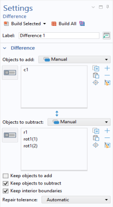
Select the object c1 only to add it to the Objects to add list in the Settings window for Difference.
|
|
1
|
|
2
|
Select the object dif1 only.
|
|
2
|
Go to the Settings window for Scale. Under Scale Factor in the Factor text field, enter sc_chamfer (one of the parameters entered in the step Global Definitions - Parameters).
|
|
3
|
Select the object rot2 only.
|
|
2
|
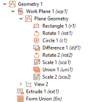
Select the objects r1, rot1(1), rot1(2), and sca1 only. Use the Selection List to select the objects if required.
|
|
2
|
Select the object rot2 only.
|
|
3
|
|
2
|
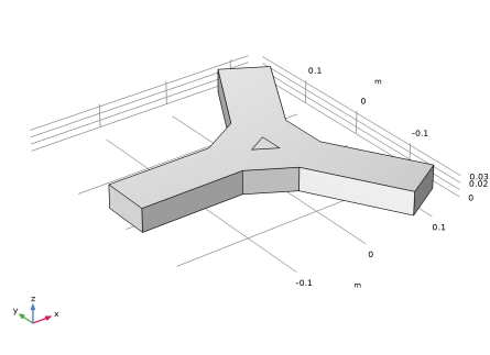
Go to the Settings window for Extrude. Under Distances from Plane in the associated table, enter 0.1/3 in the Distances (m) column.
|
 .
. and choose Rectangle
  .
. button.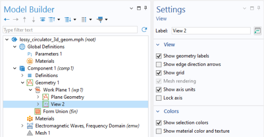
 and from the Transforms menu select Rotate
  .
. button and then click the Zoom Extents button
  in the Graphics toolbar. The geometry should match the figure so far.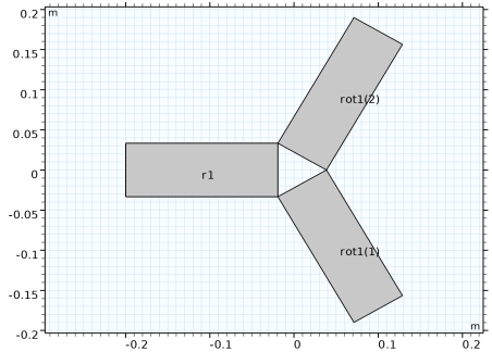
 and choose Circle
  .
. button.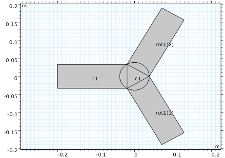
 and choose Booleans and Partitions > Difference
  .
.
 button.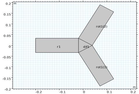
 and choose Transforms > Rotate
  .
. button.
 and choose Transforms > Scale
  .
. button.
 and choose Boolean Operations > Union
  .
. button.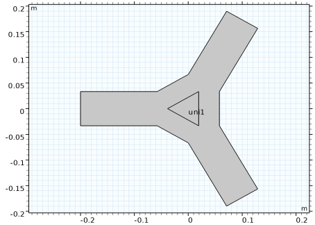
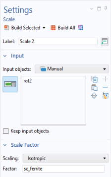
 and choose Transforms > Scale
  .
. button.
  and choose Extrude
  .
. button and then click the Zoom Extents
  button in the Graphics toolbar.
 .
. .
.