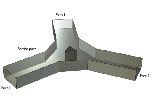
The post is magnetized by a static H0 bias field along its axis. The bias field is supplied by external permanent magnets which are not explicitly modeled in this tutorial.
One of the rectangular ports is excited by the fundamental TE10 mode. At the ports, the boundaries are transparent to the TE
10 mode. The following equation applies to the electric field vector
E inside the circulator:
where μr denotes the relative permeability tensor,
ω is the angular frequency,
σ is the conductivity tensor,
ε0 is the permittivity of vacuum,
εr is the relative permittivity tensor, and
k0 is the free space wave number. In this particular model, the conductivity is zero everywhere. Losses in the ferrite are defined using the loss tangent and the complex-valued permeability tensor. The latter is of key importance as it is also responsible for the nonreciprocal behavior. The material expressions are discussed in the next section for reference.
Complete treatises on the theory of magnetic properties of ferrites can be found in Ref. 1 and
Ref. 2. The model assumes that the static magnetic bias field,
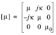
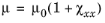
H0, is much stronger than the alternating magnetic field of the microwaves, so the quoted expressions are a linearization for a small-signal analysis around this operating point. Under these assumptions, and including losses, the anisotropic permeability of a ferrite magnetized in the positive
z direction is given by:
Here μ0 denotes the permeability of free space;
ω is the angular frequency of the microwave field;
ω0 is the precession resonance frequency (Larmor frequency) of a spinning electron in the applied magnetic bias field,
H0;
ωm is the electron Larmor frequency at the saturation magnetization of the ferrite,
Ms; and
γ is the gyromagnetic ratio of the electron. For a lossless ferrite (
α = 0), the permeability becomes infinite at
ω = ω0. In a lossy ferrite (
α ≠ 0), this resonance becomes finite and is broadened. The damping factor,
α, is related to the line width,
ΔH, of the susceptibility curve near the resonance as given by the last expression above. The material data,
with an effective loss tangent of 2·10-4 and
ΔH =
3.18·103 A/m, are taken for aluminum garnet from
Ref. 2. The applied bias field is set to
H0 =
7.96·103 A/m. The electron gyromagnetic ratio is defined as the ratio between the elementary charge and the electron mass.