Tutorial Model — Packed Bed Latent Heat Storage
Thermal energy storage (TES) units are used to accumulate thermal energy from solar, geothermal, or waste heat sources. The simplest TES units are built from water tanks, where the solar energy is stored as sensible heat. These systems are called sensible heat storage (SHS) units. The thermal capacity of these tanks can be further increased by including latent heat, which gives rise to latent heat storage (LHS) units. Typically, LHS tanks contain spherical capsules filled with paraffin wax as phase change material. Paraffin is a suitable phase change material, as it is relatively inexpensive, reliable, and nontoxic, and it is commercially available for a wide range of melting temperatures.
This example is inspired by the experimental investigation found in Ref. 1. It models the flow through a packed-bed storage tank, and it includes the effects of heat transfer with phase change and local thermal nonequilibrium (LTNE) while charging the LHS unit.
Figure 2: Latent heat storage unit.
Model definition
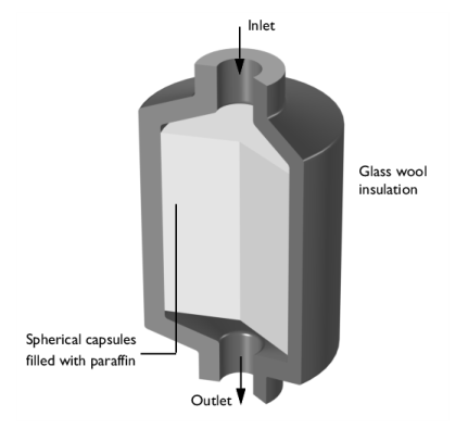
Paraffin-filled spherical capsules with a diameter of dp = 55 mm are stored in a tank of 36 cm in diameter and 47 cm in height. The porosity of this bed is 
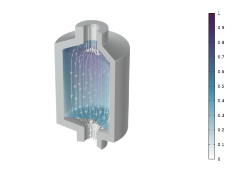
εp = 0.49. The model geometry is shown in Figure 2.
The material properties of paraffin wax are listed in the following table.
Density ρ (kg/m3)
Heat Capacity, Cp (J/(kg·K))
Geometry, material properties, and operating conditions are taken from Ref. 1.
The initial temperature in the tank is set to 32°C. Warm water flows through the tank with a flow rate of Vin = 2 l/min. During thermal charging the water is continuously heated up by a solar collector that delivers a power of Qu = 375 W. The temperature difference at the tank’s inlet and outlet is given by the relation
(1)
Here, Tin and Tout are the inlet and outlet temperatures, and ρ and Cp are the density and heat capacity of water.
Ergun equation describes non-Darcian flow through the packed bed, which estimates the pressure drop as a function of the velocity field u
(2)
here, μ (Pa·s) and ρ (kg/m3) are the viscosity and density of water, dp (m) is the spheres’ diameter, and εp the bed porosity. The permeability κ (m2) of the packed bed is given by
(3)
The Reynolds number in the packed bed can be estimated as
(4)
The maximum velocity in the tank, v, is about 6 mm/s, which implies a Reynolds number of about 600. For this Reynolds number the flow field is assumed to be independent of the temperature distribution, such that a stationary field can be computed before running the thermal simulation. This is a reasonable simplification that reduces the computational effort.
The relative large diameter of the capsules as compared to the tank dimensions suggests a significant temperature difference between the encapsulated paraffin and the surrounding water flow, thus a local thermal nonequilibrium (LTNE) approach is considered in the example. The heat transferred from the paraffin-filled capsules to the water can be written as a heat source
(5)
Here, Ts and Tf are the paraffin and water temperatures, and qsf (W/(m3·K)) is the interstitial convective heat transfer coefficient, which for spherical capsules reads
(6)
The interstitial heat transfer coefficient hsf follows a Nusselt number correlation (see the Local Thermal Nonequilibrium section in the documentation for more information). Convection inside the capsules is neglected, thus the paraffin wax is treated as a solid or immobile liquid.
Results
The tank reaches a temperature of 70°C after approximately 11 hours. The resulting velocity and temperature distribution is shown in Figure 3.
Figure 3: Velocity field (streamlines) with the gray color indicating the pressure and temperature field (color) after about 11 hours of thermal charging.
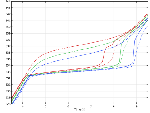
Figure 4 shows the evolution of the paraffin temperature, water temperature and the weighted average (porous medium) temperature at three different points located in the central axis of the tank. During the phase change, the encapsulated paraffin is not in thermal equilibrium with the surrounding water. Measuring the water temperature alone at the inlet or outlet does not give accurate information about neither the temperature inside the capsules nor the phase in which the paraffin wax is.
Figure 4: Evolution of water (dashed), paraffin (dotted) and average porous medium temperature (solid) during phase change for top (red), center (green) and low (blue) position.
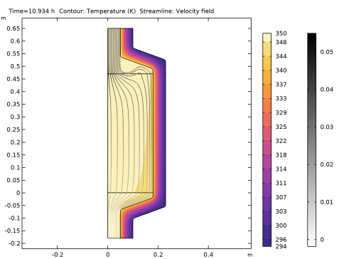
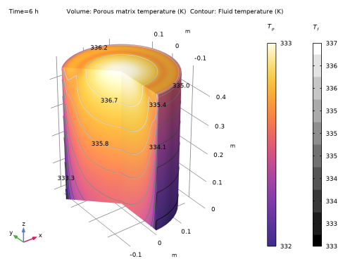
The temperature distribution after 6 hours, during the phase change, is shown in the Figure 5. The pellets remain nearly constant at 333 K, while the fluid temperature ranges between 333 K and 337 K, indicating that thermal equilibrium has not yet been reached.
Figure 5: Porous matrix (paraffin pellets) and fluid temperature after 6 hours.
The evolution of the phase distribution changes as the paraffin wax warms up. Liquid paraffin appears after approximately 4 hours, when water heats up the paraffin wax to its melting temperature of 60°C. The wax is completely molten after about 10 hours. The latent heat storage tank is considered fully charged as soon as a temperature of 70°C is reached everywhere in the tank, which happens after approximately 13 hours.
Figure 6: Paraffin solid phase (blue) and liquid phase (yellow) after 7 hours of thermal charging the LHS unit.
Figure 6 shows the paraffin phase distribution after 7 hours. Near the walls, where the flow velocity is negligible, the phase transition has not yet begun and the paraffin wax is still solid, while it is melted in the center of the tank.
References
1. N. Nallusamy and others, “Study on performance of a packed bed latent heat thermal energy storage unit integrated with solar water heating system,” Journal of Zhejiang University-SCIENCE A, vol. 7, pp. 1422–1430, 2006.