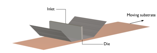
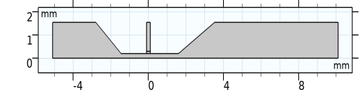
This model uses a 2D cross section of the die shown in Figure 6, assuming out-of-plane invariance. See also
Slot-Die Coating with Channel Defect in the Polymer Flow Module Application Library for a 3D model of slot-die coating. The inlet for the coating fluid is at the top of the die, as shown in
Figure 7, and there are open boundaries at both ends. The bottom boundary is the coating substrate, which is moving at the coating velocity.
The inlet fluid velocity is increases smoothly from 0 m/s to
0.1 m/s. Both the upstream and downstream boundaries of the model are specified as open boundaries. The corresponding inlet and outlet boundary conditions must also be set in the Phase Field in Fluids interface together with the initial values for both fluids to correctly define the position of the initial interface. For the moving substrate, a Moving Wall boundary condition with a Navier slip condition is used.
Figure 8 shows the evolution of the coating fluid interface for
t = 0.03 s,
t = 0.06 s, and
t = 0.2 s.
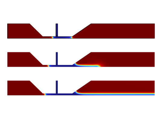
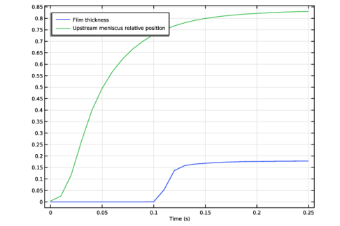
The coating film attains a constant thickness downstream of the die at t = 0.2 s. The film forms upstream and downstream menisci with the upstream and downstream walls of the die. As the substrate speed increases or the inlet velocity decreases, the upstream meniscus is pulled closer to the slot, eventually causing defects in the coating film. The evolution of the film thickness and position of the upstream meniscus as a function of time is shown in
Figure 9.