|
•
|
Source type. This determines whether the generator acts like a Voltage source (the default) or Power source. When Voltage source is selected:
|
|
-
|
|
-
|
|
•
|
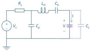
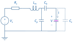
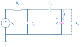
Enter the Series resistance Rs (SI unit: Ω) of the generator. This corresponds to the impedance the generator and is 50 Ω (the default value) in most practical applications.
|
|
•
|
Enter the Parallel capacitance Cp (SI unit: F) which corresponds to the capacitance parallel to the plasma. When the Circuit type is L–network or Reversed L–network, this value can be computed to ensure proper matching.
|
|
|
Computing the Plasma Impedance: Application Library path Plasma_Module/Capacitively_Coupled_Plasmas/computing_plasma_impedance
|
|
•
|
When the Circuit type is L–network or Reversed L–network, enter the Series inductance (SI unit: H). This value can also be computed to obtain a proper match.
|
|
•
|
Enter the Source frequency fp (SI unit: Hz) of the generator. This value must be consistent with the value given for the Period property of the physics interface. See Using Consistent Source Frequencies and Period Settings for further information.
|
|
•
|
Enter the Source phase α (dimensionless) of the generator. The default is zero and this rarely needs to be changed.
|
|
•
|
Include blocking capacitor. When this is active, enter the Blocking capacitance Cb (SI unit: F). This places a blocking capacitor between the plasma and the external circuit which will shield any accumulated surface charges on the electrode.
|
|
•
|
Include stray capacitance. When this is active, enter the Stray capacitance Cs (SI unit: F). This adds an additional parallel capacitance across the plasma corresponding to stray leads or the vacuum capacitance of the system. The presence of a stray capacitance can lead to an impedance mismatch between the generator and plasma in a system which would otherwise be perfectly matched.
|