Nonisothermal Pipe Flow
Next, specify the physics feature settings, including the flow and temperature conditions, as well as the friction correlations to be applied to the pipe segments.
Pipe Properties 1
1
2
-
-
In the di text field, type 20[mm]
3
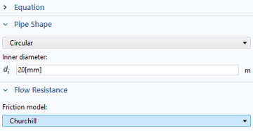
In this example, the default Churchill friction model can be applied. In many of the Settings windows in the COMSOL Desktop, there is an Equation section that you can expand. This shows you the equations employed by the current setting. In this case, the correlations for the default friction factor model Churchill is displayed. Also, if you are interested in the underlying theory of any Settings window, press F1 or the Help button . This takes you to the documentation section describing the current Settings window.
4
Pipe Properties 2
Now you can assign additional different properties to a new group of pipe segments.
1
2
3
From the Selection list, choose Feed and Return Pipes.
4
-
-
In the di text field, type 50[mm].
-
Temperature 1
1
2
Wall Heat Transfer 1
The Wall Heat Transfer feature accounts for the thermal resistance between the fluid inside the pipe and the surrounding medium, and it is applied to all sections of the system submerged below the water level.
1
2
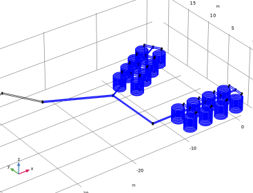
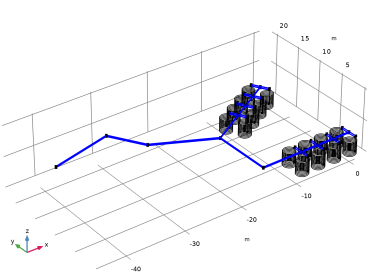
From the Selection list, choose Submerged pipes. The first two segments of the main feed and return pipes are situated above the water surface and are therefore and are not included in this feature.
3
The Wall Heat Transfer feature consists of three components: the internal film resistance, which accounts for heat transfer from the fluid to the wall; the wall layer, which models heat conduction through the pipe material; and the external resistance, which represents heat transfer from the outer wall surface to the external environment.
Internal Film Resistance 1
In the Physics toolbar, click  Attributes and choose Internal Film Resistance. This adds an automatic calculation of the heat transfer coefficient, based on the Nusselt number.
Wall Layer 1
Next, define the properties of the polyethylene pipe walls by adding a wall layer.
1
2
-
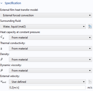
From the k list, choose User defined.
-
-
From the Δw list, choose User defined.
-
More than one Wall Layer can be added if you want a multilayered pipe wall.
External Film Resistance
1
The external flow velocity of 0.2 m/s represents the mild pond current. This velocity is sufficient to classify the heat transfer outside the pipes as forced convection.
2
-
-
-
In the uext text field, type 0.2[m/s].
The temperature dependent material properties of water are all taken from the Materials node added earlier.
Inlet 1
1
2
3
-
-
In the qv,0 text field, type 4[l/s] (as in liters/second).
The outlet condition is already set in the default node Pressure 1.
Heat Outflow 1
1
2