Geometry
Note: The location of the files used in this example varies based on your installation. For example, if the installation is on your hard drive, the file path is similar to C:\ProgramĀ Files\COMSOL\COMSOL64\Multiphysics\applications\.
Begin by defining the geometry of the piping system. Because these systems consist of multiple segments, create selections for different sections to simplify the model setup.
Start by creating the pipe system geometry. Since piping systems contain numerous segments, create selections for various parts of the system to facilitate an efficient and structured model setup. You can simplify this by inserting a prepared geometry sequence from a file.
1
2
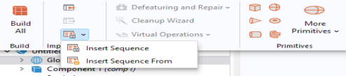
Browse to the application library folder and under Pipe_Flow_Module\Heat_Transfer double-click the file geothermal_heating_geom_sequence.mph.
3
You can at a later time inspect the geometry sequence in the Model Builder tree in detail if you want to learn how to build such a geometry from scratch.
Definitions
Now input the required data through the use of interpolation tables.
Interpolation 1
The pond water is stratified, with a temperature gradient along the depth. This profile, previously measured, will be implemented using an interpolation table.
1
Note: On Linux and Mac, the Home toolbar refers to the specific set of controls near the top of the Desktop.
2
In the Function name text field, type T_pond. In the Label text field, type Pond Temperature.
3
4
-
-