The Free Shape Boundary feature (

) can be added from the model tree under
Component using the
Shape Optimization context menu. The selection of the feature has to be adjacent to a
Free Shape Domain. The
Free Shape Boundary feature includes the following settings:
When the Preserve continuity of normals at symmetry boundaries is
Enabled, the normal vector will be fixed at edges (points in 2D) between the
Free Shape Boundary feature and the
Symmetry/Roller feature. The
User-defined option allows only fixing the normal at some of the relevant edges.
Similarly, when the Preserve continuity of normals between free shape boundary features is
Enabled, no kinks will be introduced on edges (points in 2D) between different
Free Shape Boundary features, assuming that the boundaries are initially joined continuously.
Select the Coordinate system for controls among the
Base Vector System features in the component. This section is only visible when the
Maximum displacement is
User-defined.
The default value for the Maximum displacement field is 5% of the geometry bounding box.
Pick a Small,
Medium, or
Large filter radius
Rmin, corresponding to 1, 1.5, and 2 times the
Maximum displacement dmax. Alternatively, you can set a
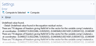
User defined filter radius and enter a custom value in the associated test field (default: 10% of the geometry bounding box). A small value can give rise to error messages such as that in
Figure 3-1.
You can set an initial value d0 for the control variable field that is different from zero, but oftentimes it is better to modify the initial geometry directly instead.