Solid Mechanics (solid)
1
In the Model Builder under Component 1, click Solid Mechanics
.
2
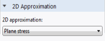
In the Settings window for Solid Mechanics locate the 2D Approximation section. From the 2D approximation list, choose Plane stress.
Roller 1
Use a Roller condition to represent the mirror symmetry boundary. If you have access to the Structural Mechanics Module, you can use a Symmetry condition instead.
1
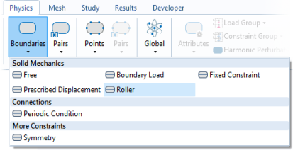
In the Physics toolbar click Boundaries
and choose Roller.
2
Select Boundary 6 only.
Note:
There are many ways to select geometric entities. When you know the geometric entity to add, such as in this exercise, you can click the Paste Selection button
and enter the boundary number in the Selection field. For more information about selecting geometric entities in the Graphics window, see the
COMSOL Multiphysics Reference Manual
.
Prescribed Displacement 1
Add a prescribed displacement condition for the lower-left corner of the beam.
1
In the Physics toolbar click Boundaries
and choose Prescribed Displacement.
2
Select Boundary 1 only.
3
Check the box with the label Prescribed in y direction.
This will support the beam in the corner, but due the vertical alignment of the boundary, there will be no support for bending in the corner.
Boundary Load 1
Since this is a linear problem, the magnitude of the applied force does not affect the optimal topology.
1
In the Physics toolbar click Boundaries
and choose Boundary Load.
2
Select Boundary 5 only.
3
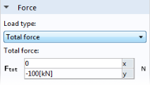
In the Settings window for Boundary Load locate the Force section.
-
From the Load type list, choose Total force.
-
Specify the
F
tot
vector as
-100[kN]
in the y direction