Symmetry
Use the Symmetry node to specify that some exterior boundaries of the model geometry either represent planes of reflection symmetry, where incoming and outgoing fluxes are equal; or the start and end planes for sector symmetry.
Only one Symmetry node may be added to each instance of the Free Molecular Flow physics interface. It is not recommended to use the Symmetry node together with the obsolete Plane Symmetry node in the same interface.
When assigning selections for the symmetry planes, it is important that each selection only includes surfaces that are coplanar. For example, you should not add two surfaces to the selection list for First Reflection Plane if they are oriented at an angle with each other; even if they are parallel, they should not both be selected if there is some normal displacement between them.
However, it is also important not to miss any surfaces that do lie in the same symmetry plane, since adding boundaries to a selection list will override other boundary conditions, such as the default Wall, on those same boundaries.
For all of the supported symmetry types, the selected boundaries must be planar and cannot be curved. Only boundaries on the exterior of the physics interface domain selection may be selected.
Symmetry
Select an option from the Type of symmetry list. The default is One symmetry plane. The option selected from this list changes which selection inputs are displayed in the settings window. For 2D axisymmetric models, only the One symmetry plane option is supported, and the selected boundaries should always be perpendicular to the z-axis.
For One symmetry plane, only the selection input for the First Reflection Plane is shown.
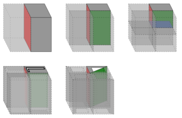
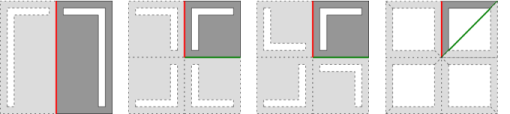
For Two perpendicular symmetry planes, the selection inputs for the First Reflection Plane and Second Reflection Plane are shown. The boundaries selected for both reflection planes should be perpendicular to each other.
For Three perpendicular symmetry planes (3D only), the selection inputs for the First Reflection Plane, Second Reflection Plane, and Third Reflection Plane are shown. The boundaries selected for all three reflection planes should be mutually perpendicular.
For Sector symmetry, the selection inputs for the Sector Start Plane and Sector End Plane are shown. The line where the two sector planes meet is the axis of rotation for n-fold rotation symmetry, where n is the Number of sectors specified in the Sector Symmetry section.
For Sector symmetry, the selection inputs for the First Reflection Plane and Sector Start Plane are shown. The sector end plane is assumed to be the mirror image of the sector start plane across the reflection plane; that is, the sector itself has plane symmetry. The line where the planes meet is the axis of rotation for n-fold rotation symmetry, where n is the Number of sectors specified in the Sector Symmetry section.
Sector Symmetry
This section is shown if Sector symmetry or Sector symmetry with reflection is selected from the Type of symmetry list in the Symmetry section. Enter a value for the Number of sectors (dimensionless). The default is 4. This should be an integer representing the number of sectors that constitute a full revolution around the symmetry axis. For Sector symmetry with reflection this should be the number of full sectors after applying the reflection, not the number of half sectors.
Sketch
This section includes some illustrations of the different types of symmetry that are supported. The sketch will change depending on space dimension and on the option selected from the Type of symmetry list in the Symmetry section.
Figure 3-1: Sketches for symmetry in 2D. From left to right: single reflection plane, two reflection planes, sector symmetry, and sector symmetry with a reflection.
Figure 3-2: Sketch for a single symmetry plane in a 2D axisymmetric geometry.
Figure 3-3: Sketches for symmetry in 3D. Top row: one, two, and three reflection planes. Bottom row: sector symmetry and sector symmetry with reflection.