Molecular Flow Module Applications
The Molecular Flow Module can be applied to solve a wide range of problems within the field of vacuum science and technology. The Free Molecular Flow interface provides a comprehensive range of boundary conditions enabling a wide range of simulations. For example, the adsorption/desorption option in the Wall boundary condition enables the modeling of gas migration within a system where the molecules have a significant dwell time on the walls. Such effects typically determine the pump-down time of a vacuum system, so it is possible to quantitatively predict the effect of geometry changes and bakeout procedures on the pump-down.
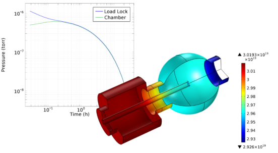
The figure below shows the evolution of the pressure in different parts of a vacuum system when water is introduced through a load-lock. Additionally, the concentration of water molecules on the surface of the system is illustrated at a particular point in time. A high concentration of water molecules is present on the surfaces of the load lock chamber at the start of the simulation and these slowly migrate through the system as water is removed by a pump in the main chamber. The pressure drops accordingly. The concentration is higher in the load lock chamber (on the left) than in the main chamber (on the right). In the vicinity of the pump (on the far right), the concentration is further reduced.
Figure 2:
Upper Left: Pressure at different points in a vacuum system after the load lock is opened up to the main chamber. Lower right: The concentration of water molecules (molecules/m
2
) on the surfaces of the system at a particular point in time.
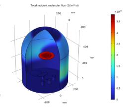
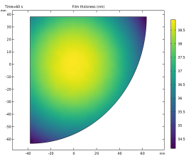
The Molecular Flow interface also includes features to model thermal evaporation and deposition. The figure below shows the flux of gold molecules arriving on the surfaces within an evaporator system (left) and the resulting film thickness (right) produced on the surface of a wafer segment mounted within the system.
Figure 3:
Left: Molecular flux resulting from an evaporative source at the base of a chamber. Right: Resulting film thickness on a sample mounted in the chamber after 60 s of evaporation.
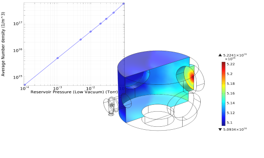
The Molecular Flow interface is also extremely flexible. It is possible to model the transport of several species by adding additional dependent variables. The different species can interact on the surfaces of the flow geometry. Powerful equation-based modeling capabilities are built into the software. For example, it is straightforward to combine a molecular flow model with an empirical model for transitional flow within a tube.
Figure 4
shows an example in which this approach is used to model the number density on the high vacuum side of a differentially pumped vacuum system.
Figure 4:
Upper left: Number density on the high vacuum side of a differentially pumped system (the average number density on the flange opposite the inlet from the low vacuum side is given). Lower right: Number density within the high vacuum chamber when the pressure on the low vacuum side is 10
-4
Torr. The inlet from the low vacuum side is on the left and the pump is at the base of the chamber. This model accounts for the transitional flow through the tube connecting the low vacuum and high vacuum chambers by using an empirical expression.