|
|
|

|
1217 cm-1
|
|
1
|
|
2
|
In the Select Physics tree, select Optics > Wave Optics > Electromagnetic Waves, Frequency Domain (ewfd).
|
|
3
|
Click Add.
|
|
4
|
Click Add.
|
|
5
|
Click
|
|
6
|
|
7
|
Click
|
|
1
|
|
2
|
Browse to the model’s Application Libraries folder and double-click the file vertical_cavity_surface_emitting_laser_geom_sequence.mph.
|
|
3
|
|
4
|
|
5
|
|
6
|
|
1
|
|
2
|
|
1
|
|
2
|
|
3
|
|
4
|
Browse to the model’s Application Libraries folder and double-click the file vertical_cavity_surface_emitting_laser_general_parameters.txt.
|
|
1
|
|
2
|
|
3
|
|
4
|
Browse to the model’s Application Libraries folder and double-click the file vertical_cavity_surface_emitting_laser_material_parameters.txt.
|
|
1
|
In the Model Builder window, under Component 1 (comp1) click Electromagnetic Waves, Frequency Domain (ewfd).
|
|
2
|
In the Settings window for Electromagnetic Waves, Frequency Domain, locate the Out-of-Plane Wave Number section.
|
|
3
|
In the m text field, type 1. This will give you the expected rotation angle variation, discussed above.
|
|
1
|
|
2
|
|
4
|
In the Settings window for Scattering Boundary Condition, locate the Scattering Boundary Condition section.
|
|
5
|
|
1
|
|
1
|
In the Model Builder window, under Component 1 (comp1) right-click Materials and choose Blank Material.
|
|
2
|
|
3
|
Locate the Geometric Entity Selection section. From the Geometric entity level list, choose Boundary.
|
|
5
|
Locate the Material Contents section. In the table, enter the following settings:
|
|
1
|
|
2
|
|
3
|
|
4
|
Locate the Material Contents section. In the table, enter the following settings:
|
|
1
|
|
2
|
|
3
|
|
4
|
Locate the Material Contents section. In the table, enter the following settings:
|
|
1
|
|
2
|
|
3
|
|
4
|
Locate the Material Contents section. In the table, enter the following settings:
|
|
1
|
|
2
|
|
3
|
|
4
|
Locate the Material Contents section. In the table, enter the following settings:
|
|
1
|
In the Model Builder window, under Component 1 (comp1) > Materials right-click AlGaAs (mat3) and choose Duplicate.
|
|
2
|
|
3
|
|
4
|
Locate the Material Contents section. In the table, enter the following settings:
|
|
1
|
|
2
|
|
3
|
|
4
|
Locate the Material Contents section. In the table, enter the following settings:
|
|
1
|
In the Model Builder window, under Component 1 (comp1) > Materials right-click Air Superstrate (mat1) and choose Duplicate.
|
|
2
|
|
3
|
|
5
|
Locate the Material Contents section. In the table, enter the following settings:
|
|
1
|
In the Model Builder window, under Component 1 (comp1) right-click Definitions and choose Variables.
|
|
2
|
|
1
|
|
2
|
|
3
|
|
1
|
|
2
|
|
3
|
|
4
|
|
5
|
|
6
|
Locate the Element Size Parameters section.
|
|
7
|
|
1
|
|
2
|
|
3
|
|
4
|
Locate the Element Size Parameters section. In the Maximum element size text field, type lda0/6/n_AlGaAs.
|
|
1
|
|
2
|
|
3
|
|
4
|
Locate the Element Size Parameters section. In the Maximum element size text field, type lda0/6/n_QW.
|
|
1
|
|
2
|
|
3
|
|
1
|
|
2
|
|
3
|
|
4
|
Locate the Element Size Parameters section. In the Maximum element size text field, type lda0/6/n_AlAs.
|
|
1
|
|
2
|
|
3
|
|
4
|
Locate the Element Size Parameters section. In the Maximum element size text field, type lda0/6/n_AlOx.
|
|
1
|
|
2
|
Drag and drop below AlOx.
|
|
3
|
|
1
|
|
2
|
|
3
|
|
4
|
|
5
|
Locate the Physics and Variables Selection section. Select the Modify model configuration for study step checkbox.
|
|
6
|
|
7
|
Click
|
|
8
|
|
1
|
|
1
|
In the Model Builder window, expand the Results > Eigenfrequencies (ewfd) node, then click Eigenfrequencies (ewfd).
|
|
2
|
|
4
|
|
1
|
|
2
|
|
3
|
|
4
|
Click
|
|
5
|
In the Paste Selection dialog, type 115 in the Selection text field. This corresponds to the point where the top boundary crosses the symmetry axis.
|
|
6
|
|
7
|
|
8
|
|
1
|
In the Model Builder window, under Component 1 (comp1) click Electromagnetic Waves, Frequency Domain 2 (ewfd2).
|
|
2
|
In the Settings window for Electromagnetic Waves, Frequency Domain, click to expand the Equation section.
|
|
3
|
|
4
|
From the Frequency list, choose User defined. In the f text field, type freq1. A dependent variable with this name will be added later.
|
|
5
|
|
1
|
In the Model Builder window, under Component 1 (comp1) > Electromagnetic Waves, Frequency Domain 2 (ewfd2) click Initial Values 1.
|
|
2
|
|
3
|
|
1
|
In the Model Builder window, under Component 1 (comp1) > Electromagnetic Waves, Frequency Domain (ewfd), Ctrl-click to select Scattering Boundary Condition 1 and Impedance Boundary Condition 1.
|
|
2
|
Right-click and choose Copy.
|
|
1
|
In the Model Builder window, under Component 1 (comp1) right-click Electromagnetic Waves, Frequency Domain 2 (ewfd2) and choose Paste Multiple Items.
|
|
2
|
|
3
|
In the Show More Options dialog, in the tree, select the checkbox for the node Physics > Equation Contributions.
|
|
4
|
|
5
|
Click OK.
|
|
1
|
|
2
|
|
3
|
Locate the Global Equations section. In the table, enter the following settings:
|
|
4
|
Click to expand the Discretization section. From the Value type when using splitting of complex variables list, choose Real, as the frequency is a real quantity.
|
|
5
|
|
6
|
|
7
|
|
8
|
Click OK.
|
|
9
|
|
10
|
Click
|
|
11
|
|
12
|
|
13
|
Click OK.
|
|
1
|
|
2
|
|
3
|
Locate the Global Equations section. In the table, enter the following settings:
|
|
4
|
|
5
|
|
6
|
|
7
|
Click OK.
|
|
1
|
|
2
|
Go to the Add Study window.
|
|
3
|
|
4
|
Find the Physics interfaces in study subsection. In the table, clear the Solve checkbox for Electromagnetic Waves, Frequency Domain (ewfd).
|
|
5
|
Click the Add Study button in the window toolbar.
|
|
6
|
|
1
|
|
2
|
|
3
|
Select the Modify model configuration for study step checkbox.
|
|
4
|
|
5
|
|
6
|
|
7
|
Click
|
|
1
|
|
2
|
In the Model Builder window, expand the Solution 2 (sol2) node, then click Compile Equations: Stationary.
|
|
3
|
|
4
|
Select the Split complex variables in real and imaginary parts checkbox. This will make sure that the real variables defined in the Global Equations will be treated correctly when solving.
|
|
5
|
|
1
|
|
2
|
|
3
|
|
1
|
|
2
|
|
3
|
|
4
|
Locate the Expressions section. In the table, enter the following settings:
|
|
5
|
Click
|
|
1
|
|
2
|
|
1
|
|
2
|
|
3
|
|
4
|
|
5
|
|
6
|
Locate the Selections of Resulting Entities section. Find the Cumulative selection subsection. From the Contribute to list, choose GaAs Layers.
 |
|
1
|
|
2
|
|
3
|
|
4
|
|
5
|
|
6
|
|
7
|
Click
|
|
8
|
|
1
|
In the Model Builder window, under Component 1 (comp1) right-click Materials and choose Blank Material.
|
|
2
|
|
4
|
Locate the Material Contents section. In the table, enter the following settings:
|
|
1
|
|
2
|
Go to the Add Physics window.
|
|
3
|
|
4
|
Click the Add to Component 1 button in the window toolbar.
|
|
5
|
|
1
|
In the Settings window for Electromagnetic Waves, Frequency Domain, locate the Out-of-Plane Wave Number section.
|
|
2
|
|
1
|
|
2
|
|
3
|
Click
|
|
1
|
In the Model Builder window, expand the Far-Field Domain 1 node, then click Far-Field Calculation 1.
|
|
2
|
|
3
|
Click
|
|
4
|
Click
|
|
5
|
|
6
|
|
1
|
|
1
|
|
2
|
|
3
|
|
5
|
|
6
|
Locate the Element Size Parameters section.
|
|
7
|
|
8
|
|
9
|
Click
|
|
1
|
|
2
|
Go to the Add Study window.
|
|
3
|
|
4
|
Right-click and choose Add Study.
|
|
5
|
|
1
|
|
2
|
|
3
|
|
4
|
Locate the Physics and Variables Selection section. Select the Modify model configuration for study step checkbox.
|
|
5
|
|
6
|
Click
|
|
7
|
|
8
|
Click
|
|
9
|
|
1
|
In the Model Builder window, expand the Results > Eigenfrequencies (ewfd3) node, then click Eigenfrequencies (ewfd3).
|
|
2
|
|
4
|
|
1
|
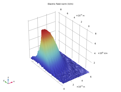
In the Model Builder window, expand the Results > Electric Field (ewfd3) node, then click Electric Field (ewfd3).
|
|
2
|
|
3
|
Clear the Plot dataset edges checkbox.
|
|
1
|
|
2
|
|
3
|
Click
|
|
4
|
|
5
|
Click OK.
|
|
6
|
|
7
|
|
1
|
|
2
|
|
3
|
|
1
|
|
2
|
|
3
|
Find the Angles subsection. In the Number of angles text field, type 540. This improves the resolution and smoothness of the plot.
|
|
4
|
|
1
|
In the Model Builder window, expand the Results > 3D Far Field (ewfd3) node, then click Radiation Pattern 1.
|
|
2
|
|
3
|
|
4
|
|
1
|
|
2
|
Go to the Add Physics window.
|
|
3
|
|
4
|
Click the Add to Component 1 button in the window toolbar.
|
|
5
|
|
1
|
In the Settings window for Electromagnetic Waves, Frequency Domain, locate the Out-of-Plane Wave Number section.
|
|
2
|
|
1
|
In the Model Builder window, under Component 1 (comp1) > Electromagnetic Waves, Frequency Domain 4 (ewfd4) click Initial Values 1.
|
|
2
|
|
3
|
|
1
|
|
2
|
|
3
|
Locate the Global Equations section. In the table, enter the following settings:
|
|
4
|
Locate the Discretization section. From the Value type when using splitting of complex variables list, choose Real.
|
|
5
|
|
6
|
|
7
|
|
8
|
Click OK.
|
|
9
|
|
10
|
Click
|
|
11
|
|
12
|
|
13
|
Click OK.
|
|
1
|
|
2
|
|
3
|
Locate the Global Equations section. In the table, enter the following settings:
|
|
4
|
|
5
|
|
6
|
|
7
|
Click OK.
|
|
1
|
|
2
|
Go to the Add Study window.
|
|
3
|
|
4
|
Click the Add Study button in the window toolbar.
|
|
1
|
|
2
|
|
3
|
Select the Modify model configuration for study step checkbox.
|
|
4
|
|
5
|
Click
|
|
6
|
|
7
|
Click
|
|
8
|
|
9
|
Click
|
|
10
|
|
1
|
|
2
|
|
3
|
|
4
|
|
5
|
|
1
|
|
2
|
|
3
|
Click
|
|
4
|
|
5
|
Click OK.
|
|
1
|
|
2
|
|
3
|
|
4
|
Locate the Expressions section. In the table, enter the following settings:
|
|
5
|
Click
|
|
1
|
|
2
|
Click
|
|
1
|
|
2
|
|
3
|
|
4
|
Browse to the model’s Application Libraries folder and double-click the file vertical_cavity_surface_emitting_laser_geometry_parameters.txt.
|
|
1
|
|
2
|
|
3
|
|
4
|
Browse to the model’s Application Libraries folder and double-click the file vertical_cavity_surface_emitting_laser_dbr_pair_parameters.txt.
|
|
1
|
|
2
|
|
3
|
|
4
|
|
5
|
|
6
|
|
7
|
Locate the Selections of Resulting Entities section. Select the Resulting objects selection checkbox.
|
|
8
|
|
1
|
|
2
|
|
3
|
|
4
|
|
5
|
|
6
|
|
7
|
|
1
|
|
2
|
|
4
|
Click to expand the Domain Selections section. Click to select row number 1 in the table.
|
|
5
|
Click New Cumulative Selection.
|
|
6
|
In the New Cumulative Selection dialog, type AlGaAs Layers in the Name text field. The cumulative selections will later be used when assigning the materials and when building the mesh sequence.
|
|
7
|
Click OK.
|
|
8
|
|
10
|
Click New Cumulative Selection.
|
|
11
|
|
12
|
Click OK.
|
|
1
|
|
2
|
|
3
|
Click in the Graphics window and then press Ctrl+A to select both objects.
|
|
4
|
|
5
|
|
6
|
|
7
|
|
8
|
Click
|
|
9
|
|
1
|
|
2
|
|
3
|
|
4
|
|
5
|
|
6
|
Locate the Selections of Resulting Entities section. Find the Cumulative selection subsection. From the Contribute to list, choose AlGaAs Layers.
|
|
7
|
Click
|
|
8
|
|
1
|
|
2
|
In the Settings window for Rectangle, type Bottom GaAs Layer in Lambda Cavity in the Label text field.
|
|
3
|
|
4
|
|
5
|
Locate the Selections of Resulting Entities section. Find the Cumulative selection subsection. From the Contribute to list, choose GaAs Layers.
|
|
6
|
Click
|
|
7
|
|
1
|
|
2
|
|
3
|
|
4
|
|
5
|
|
6
|
Locate the Selections of Resulting Entities section. Find the Cumulative selection subsection. Click New.
|
|
7
|
|
8
|
Click OK.
|
|
9
|
|
10
|
|
1
|
|
2
|
|
3
|
|
4
|
|
5
|
Locate the Selections of Resulting Entities section. Find the Cumulative selection subsection. Click New.
|
|
6
|
|
7
|
Click OK.
|
|
8
|
|
9
|
|
1
|
In the Model Builder window, under Component 1 (comp1) > Geometry 1 right-click Bottom GaAs Layer in Lambda Cavity (r2) and choose Duplicate.
|
|
2
|
|
3
|
|
4
|
Click
|
|
5
|
|
1
|
|
2
|
In the Settings window for If, type If Bottom AlGaAs Layer in Oxide Window is Finite in the Label text field.
|
|
3
|
|
1
|
In the Model Builder window, under Component 1 (comp1) > Geometry 1 right-click Top Layer in Bottom DBR (r1) and choose Duplicate.
|
|
2
|
In the Settings window for Rectangle, type Bottom AlGaAs Layer in Oxide Window in the Label text field.
|
|
3
|
Locate the Size and Shape section. In the Height text field, type t_AlGaAs_oxide_window_bottom_layer.
|
|
4
|
|
1
|
|
2
|
In the Settings window for End If, type End If Bottom AlGaAs Layer in Oxide Window is Finite in the Label text field.
|
|
3
|
Click
|
|
4
|
|
1
|
In the Model Builder window, under Component 1 (comp1) > Geometry 1 right-click Bottom AlGaAs Layer in Oxide Window (r6) and choose Duplicate.
|
|
2
|
Drag and drop Bottom AlGaAs Layer in Oxide Window 1 (r7) below End If Bottom AlGaAs Layer in Oxide Window is Finite (endif1).
|
|
3
|
|
4
|
|
5
|
|
6
|
Locate the Position section. In the z text field, type t_bottom_DBR+t_cavity+t_AlGaAs_oxide_window_bottom_layer.
|
|
7
|
Locate the Selections of Resulting Entities section. Find the Cumulative selection subsection. Click New.
|
|
8
|
|
9
|
Click OK.
|
|
10
|
|
11
|
|
1
|
|
2
|
|
3
|
|
4
|
|
5
|
Locate the Selections of Resulting Entities section. Find the Cumulative selection subsection. Click New.
|
|
6
|
|
7
|
Click OK.
|
|
8
|
|
9
|
|
1
|
In the Model Builder window, under Component 1 (comp1) > Geometry 1, Ctrl-click to select If Bottom AlGaAs Layer in Oxide Window is Finite (if1), Bottom AlGaAs Layer in Oxide Window (r6), and End If Bottom AlGaAs Layer in Oxide Window is Finite (endif1).
|
|
2
|
Right-click and choose Duplicate.
|
|
1
|
In the Settings window for If, type If Second AlGaAs Layer in Oxide Window is Finite in the Label text field.
|
|
2
|
|
1
|
In the Model Builder window, under Component 1 (comp1) > Geometry 1 click Bottom AlGaAs Layer in Oxide Window 1 (r9).
|
|
2
|
In the Settings window for Rectangle, type Second AlGaAs Layer in Oxide Window in the Label text field.
|
|
3
|
Locate the Size and Shape section. In the Height text field, type t_AlGaAs_oxide_window_second_layer.
|
|
4
|
Locate the Position section. In the z text field, type t_bottom_DBR+t_cavity+t_AlGaAs_oxide_window_bottom_layer+t_oxide.
|
|
1
|
In the Model Builder window, under Component 1 (comp1) > Geometry 1 click End If Bottom AlGaAs Layer in Oxide Window is Finite 1 (endif2).
|
|
2
|
In the Settings window for End If, type End If Second AlGaAs Layer in Oxide Window is Finite in the Label text field.
|
|
3
|
Click
|
|
4
|
|
1
|
In the Model Builder window, under Component 1 (comp1) > Geometry 1 right-click Bottom GaAs Layer in Lambda Cavity (r2) and choose Duplicate.
|
|
2
|
|
3
|
|
4
|
Locate the Position section. In the z text field, type t_bottom_DBR+t_cavity+t_AlGaAs_oxide_window_bottom_layer+t_oxide+t_AlGaAs_oxide_window_second_layer.
|
|
5
|
Click
|
|
6
|
|
1
|
In the Model Builder window, under Component 1 (comp1) > Geometry 1 right-click DBR Pair 1 (pi1) and choose Duplicate.
|
|
2
|
|
1
|
|
2
|
|
3
|
|
4
|
|
5
|
|
6
|
|
7
|
Click
|
|
8
|