|
|
|


|
1
|
|
2
|
In the Select Physics tree, select Optics > Wave Optics > Electromagnetic Waves, Beam Envelopes (ewbe).
|
|
3
|
Click Add.
|
|
4
|
Click
|
|
5
|
In the Select Study tree, select Preset Studies for Selected Physics Interfaces > Wavelength Domain.
|
|
6
|
Click
|
|
1
|
|
2
|
|
1
|
|
2
|
|
3
|
|
4
|
|
5
|
|
6
|
|
1
|
|
2
|
|
3
|
|
4
|
|
5
|
|
6
|
|
7
|
|
1
|
|
2
|
Click in the Graphics window and then press Ctrl+A to select both objects.
|
|
3
|
|
1
|
In the Model Builder window, expand the Component 1 (comp1) > Definitions > View 1 node, then click Camera.
|
|
2
|
|
3
|
|
4
|
|
5
|
Select the Automatic update checkbox.
|
|
6
|
Click
|
|
7
|
|
1
|
In the Model Builder window, under Component 1 (comp1) right-click Materials and choose Blank Material.
|
|
2
|
|
3
|
Locate the Material Contents section. In the table, enter the following settings:
|
|
1
|
|
2
|
|
3
|
|
1
|
|
2
|
|
4
|
|
6
|
Click to select the
|
|
8
|
Click to select the
|
|
10
|
Click to select the
|
|
12
|
|
14
|
Click to select the
|
|
16
|
Click to select the
|
|
1
|
|
2
|
|
3
|
|
5
|
|
7
|
Click to select the
|
|
9
|
Click to select the
|
|
11
|
|
13
|
Click to select the
|
|
1
|
|
2
|
|
1
|
In the Model Builder window, under Component 1 (comp1) click Electromagnetic Waves, Beam Envelopes (ewbe).
|
|
2
|
|
3
|
|
4
|
|
1
|
|
3
|
In the Settings window for Matched Boundary Condition, locate the Matched Boundary Condition section.
|
|
4
|
|
5
|
|
6
|
|
7
|
|
8
|
|
9
|
|
1
|
|
2
|
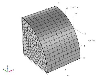
Select Point 2 only, that is the point on the optical axis (where y = 0 and z = 0). The focal point is located the distance p0 from this reference point in the propagation direction, defined by ewbe.k1.
|
|
1
|
|
1
|
|
1
|
|
3
|
|
4
|
|
1
|
|
2
|
|
3
|
Click the Custom button.
|
|
4
|
|
1
|
|
1
|
|
2
|
|
3
|
Click the Custom button.
|
|
4
|
Locate the Element Size Parameters section.
|
|
5
|
|
6
|
|
1
|
|
2
|
|
1
|
|
2
|
|
3
|
|
1
|
|
2
|
|
3
|
Click
|
|
5
|
Click to expand the Advanced Settings section. From the Use parametric solver list, choose Off, to turn off the parametric solver that otherwise would perform calculations also for intermediate intensities.
|
|
1
|
|
2
|
In the Model Builder window, expand the Solution 1 (sol1) node, then click Compile Equations: Wavelength Domain.
|
|
3
|
|
4
|
Select the Split complex variables in real and imaginary parts checkbox.
|
|
5
|
|
1
|
|
2
|
|
1
|
|
2
|
|
3
|
|
4
|
|
5
|
|
6
|
|
7
|
|
1
|
|
2
|
|
3
|
|
4
|
|
1
|
|
2
|
|
3
|
Clear the Plot dataset edges checkbox.
|
|
4
|
|
5
|
|
6
|
|
7
|
|
8
|
|
9
|
|
10
|
|
11
|
|
12
|
|
13
|
|
14
|
|
15
|
|
16
|
|
17
|
|
1
|
In the Model Builder window, under Results > Electric Field (ewbe) > Electric Field click Deformation 1.
|
|
2
|
|
3
|
|
1
|
|
2
|
|
3
|
|
4
|
|
5
|
|
6
|
|
1
|
|
2
|
|
1
|
|
2
|
|
3
|
|
4
|
|
5
|
|
1
|
|
2
|
|
3
|
|
1
|
|
2
|
|
3
|
Clear the Plot dataset edges checkbox.
|
|
4
|
|
5
|
|
6
|
|
7
|
|
1
|
|
2
|
|
3
|
|
4
|
Locate the Expressions section. In the table, enter the following settings:
|
|
5
|
Click
|
|
1
|
Go to the Table 1 window.
|
|
2
|
Click the Table Graph button in the window toolbar.
|
|
1
|
|
2
|
|
3
|
|
4
|
|
5
|
|
1
|
|
2
|
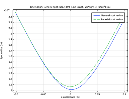
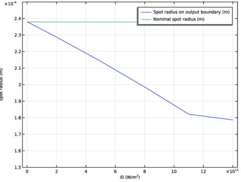
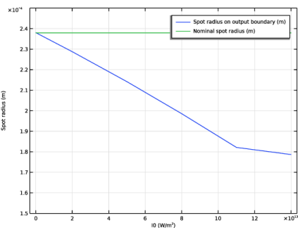
In the Settings window for 1D Plot Group, type Spot Radius on Output Boundary in the Label text field.
|
|
3
|
Locate the Plot Settings section.
|
|
4
|
|
5
|
|
6
|
|
7
|
|
8
|
In the Spot Radius on Output Boundary toolbar, click
 |
|
1
|
|
2
|
|
3
|
|
4
|
|
5
|
|
6
|
Locate the Plot Settings section.
|
|
7
|
|
1
|
|
3
|
|
4
|
|
5
|
|
6
|
|
7
|
|
8
|
|
1
|
|
2
|
|
3
|
|
4
|
Click to expand the Coloring and Style section. Find the Line style subsection. From the Line list, choose Dashed.
|
|
5
|
Locate the Legends section. In the table, enter the following settings:
|
|
6
|
|
1
|
|
2
|
|
3
|
|
4
|
Locate the Expressions section. In the table, enter the following settings:
|
|
5
|
Click
|
|
1
|
Go to the Table 2 window.
|