PDF

Designing a Metasurface Beam Deflector Using Shape Optimization
Introduction
This model is inspired by the Metasurface Beam Deflector model. In this example, optimization is applied to maximize the deflection by using shape optimization to change the position and radii of the pillars.
Model Definition
Figure 1 shows the initial geometry used for the topology optimization.
Figure 1: The initial geometry with the six cylindrical pillars.
The pillars are scaled and moved using the Transformation feature in the Shape Optimization interface, while the built-in variable for the reflection is used as the objective function.
Results and Discussion
The model performs 50 optimization iterations increasing the reflection from 85% to 92%, but the actual design changes are subtle as illustrated in Figure 2.
Figure 2: The shape optimization changes the design marginally.
Application Library path: Wave_Optics_Module/Gratings_and_Metamaterials/metasurface_beam_deflector_optimization
Modeling Instructions
This example starts from an existing model from the Wave Optics Module Application Library.
Application Libraries
1
From the File menu, choose Application Libraries.
2
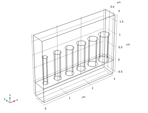
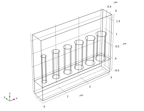
In the Application Libraries window, select Wave Optics Module > Gratings and Metamaterials > metasurface_beam_deflector in the tree.
3
Global Definitions
Parameters 2
1
In the Home toolbar, click  Parameters and choose Add > Parameters.
2
In the Settings window for Parameters, locate the Parameters section.
3
Component 1 (comp1)
Free Shape Domain 1
In the Physics toolbar, click  Optimization and choose Shape Optimization.
Symmetry/Roller 1
1
In the Shape Optimization toolbar, click  Symmetry/Roller.
2
Transformation 1
1
In the Shape Optimization toolbar, click  Transformation.
2
In the Settings window for Transformation, locate the Geometric Entity Selection section.
3
From the Selection list, choose Posts.
4
Locate the Translation section. In the table, enter the following settings:
5
Locate the Scaling section. From the Scaling type list, choose Isotropic (XY).
6
Study 1
Shape Optimization
1
In the Study toolbar, click  Optimization and choose Shape Optimization.
2
In the Settings window for Shape Optimization, locate the Optimization Solver section.
3
In the Maximum number of iterations text field, type 50.
4
Click Add Expression in the upper-right corner of the Objective Function section. From the menu, choose Component 1 (comp1) > Electromagnetic Waves, Frequency Domain > Ports > Transmittance, by order > comp1.ewfd.Torder_p1_0_op - Transmittance, order [1,0], out-of-plane.
5
Locate the Objective Function section. From the Type list, choose Maximization.
6
In the Study toolbar, click  Get Initial Value, so that a default plot is generated, which can be shown while optimizing.
Result Templates
1
In the Home toolbar, click  Windows and choose Result Templates.
2
Go to the Result Templates window.
3
In the tree, select Study 1/Solution 1 (sol1) > Transformation 1 > Shape Optimization.
4
Click the Add Result Template button in the window toolbar.
5
In the Results toolbar, click  Result Templates to close the Result Templates window.
Study 1
1
In the Settings window for Shape Optimization, click to expand the Output section.
2
From the Keep solutions list, choose First and last.
3
Select the Plot checkbox.
4
5
In the Study toolbar, click  Compute.
Results
Electric Field (ewfd)
1
In the Settings window for 3D Plot Group, locate the Data section.
2
From the Optimization solution list, choose 0.
Multislice 2
1
In the Model Builder window, expand the Electric Field (ewfd) node.
2
Right-click Results > Electric Field (ewfd) > Multislice 1 and choose Duplicate.
3
In the Settings window for Multislice, locate the Data section.
4
From the Dataset list, choose Study 1/Solution 1 (sol1).
5
Click to expand the Inherit Style section. From the Plot list, choose Multislice 1.
Transformation 1
1
Right-click Multislice 2 and choose Transformation.
2
In the Settings window for Transformation, locate the Transformation section.
3
In the X text field, type 4.
4
Click the  Go to XZ View button in the Graphics toolbar.
5
Click the  Orthographic Projection button in the Graphics toolbar.
6
Click the  Zoom Extents button in the Graphics toolbar.
Polarization Plot (ewfd)
Finally, display the polarization plot for each optimization solution.
1
In the Model Builder window, under Results click Polarization Plot (ewfd).
2
In the Settings window for 1D Plot Group, locate the Data section.
3
From the Optimization solution list, choose From list.
4
In the Optimization solution list box, select 0.
5
Locate the Legend section. From the Layout list, choose Outside graph axis area.
6
From the Position list, choose Bottom.
7
In the Number of rows text field, type 5.
8
In the Polarization Plot (ewfd) toolbar, click  Plot.
9
Clicknext to  cycle_plot_level, then choose Optimization solution.
10
Click  Plot Next.