
|
|
|


|
1
|
|
2
|
In the Select Physics tree, select Mathematics > PDE Interfaces > Lower Dimensions > Coefficient Form Boundary PDE (cb).
|
|
3
|
Click Add.
|
|
4
|
In the Select Physics tree, select Optics > Wave Optics > Electromagnetic Waves, Frequency Domain (ewfd).
|
|
5
|
Click Add.
|
|
6
|
Click
|
|
7
|
|
8
|
Click
|
|
1
|
|
2
|
Browse to the model’s Application Libraries folder and double-click the file metalens_topology_optimization_geom_sequence.mph.
|
|
3
|
|
4
|
|
5
|
|
1
|
|
2
|
|
3
|
Locate the Parameters section. In the table, enter the following settings:
|
|
1
|
|
2
|
|
1
|
|
2
|
|
3
|
Locate the Geometric Entity Selection section. From the Geometric entity level list, choose Boundary.
|
|
4
|
|
5
|
|
6
|
|
7
|
|
8
|
Locate the Discretization section. From the Shape function type list, choose Discontinuous Lagrange.
|
|
9
|
|
1
|
|
2
|
|
3
|
|
4
|
|
5
|
|
6
|
Click OK.
|
|
7
|
In the Settings window for Coefficient Form Boundary PDE, click to expand the Discretization section.
|
|
8
|
|
9
|
|
10
|
|
11
|
Click
|
|
12
|
In the Dependent variables (1) table, enter the following settings:
|
|
1
|
In the Model Builder window, under Component 1 (comp1) > Coefficient Form Boundary PDE (cb) click Coefficient Form PDE 1.
|
|
2
|
|
3
|
|
4
|
|
5
|
Locate the Absorption Coefficient section. In the a text-field array, type 1 in the first column of the first row.
|
|
6
|
|
7
|
|
8
|
In the f text-field array, type if(Z<eps,theta_f,1-(1-theta_f)*(1-genext1(theta_m))) on the second row, so that the value of theta_m always increases going up the layers, because genext1 refers to the layer below.
|
|
9
|
Locate the Damping or Mass Coefficient section. In the da text-field array, type 0 in the first column of the first row.
|
|
10
|
|
1
|
|
2
|
|
3
|
|
4
|
|
5
|
|
6
|
|
7
|
|
1
|
|
2
|
|
3
|
|
1
|
|
2
|
|
3
|
|
4
|
|
5
|
Locate the Variables section. In the table, enter the following settings:
|
|
1
|
|
2
|
|
3
|
|
4
|
Locate the Variables section. In the table, enter the following settings:
|
|
1
|
|
2
|
|
3
|
|
5
|
Locate the Variables section. In the table, enter the following settings:
|
|
1
|
|
2
|
|
3
|
Click
|
|
5
|
Locate the Variables section. In the table, enter the following settings:
|
|
1
|
In the Model Builder window, under Global Definitions right-click Materials and choose Blank Material.
|
|
2
|
|
3
|
In the Material properties tree, select Electromagnetic Models > Refractive Index > Refractive index, imaginary part (ki).
|
|
4
|
Right-click and choose Add This Property Group to Material.
|
|
5
|
In the Material properties tree, select Electromagnetic Models > Refractive Index > Refractive index, real part (n).
|
|
6
|
Right-click and choose Add This Property Group to Material.
|
|
7
|
Locate the Material Contents section. In the table, enter the following settings:
|
|
1
|
Go to the Add Material window.
|
|
2
|
|
3
|
Click the Add to Component button in the window toolbar.
|
|
4
|
|
1
|
In the Model Builder window, under Component 1 (comp1) right-click Materials and choose More Materials > Material Link.
|
|
2
|
|
3
|
|
1
|
|
2
|
|
3
|
|
4
|
Locate the Material Contents section. In the table, enter the following settings:
|
|
1
|
In the Model Builder window, under Component 1 (comp1) click Electromagnetic Waves, Frequency Domain (ewfd).
|
|
2
|
In the Settings window for Electromagnetic Waves, Frequency Domain, locate the Out-of-Plane Wave Number section.
|
|
3
|
|
4
|
|
1
|
|
2
|
|
3
|
|
4
|
Locate the Scattering Boundary Condition section. From the Incident field list, choose Gaussian beam.
|
|
5
|
|
6
|
|
7
|
|
1
|
|
2
|
|
3
|
|
4
|
|
5
|
|
1
|
|
2
|
|
3
|
|
4
|
|
5
|
Click Replace Expression in the upper-right corner of the Expression section. From the menu, choose Component 1 (comp1) > Electromagnetic Waves, Frequency Domain > Electric > ewfd.normE - Electric field norm - V/m.
|
|
1
|
|
2
|
|
3
|
|
4
|
|
1
|
|
2
|
|
3
|
Click the Custom button.
|
|
4
|
Locate the Element Size Parameters section.
|
|
5
|
|
1
|
|
2
|
|
3
|
|
1
|
|
2
|
|
1
|
|
2
|
|
3
|
|
4
|
|
5
|
|
1
|
|
2
|
|
3
|
|
4
|
Click Add Expression in the upper-right corner of the Objective Function section. From the menu, choose Component 1 (comp1) > Definitions > comp1.obj - Objective - V/m.
|
|
5
|
|
6
|
|
7
|
|
8
|
|
9
|
|
10
|
In the Study toolbar, click
|
|
1
|
|
2
|
|
1
|
|
2
|
|
3
|
|
1
|
|
2
|
|
3
|
|
4
|
|
5
|
|
1
|
In the Model Builder window, expand the Study 1 > Solver Configurations > Solution 1 (sol1) > Optimization Solver 1 node.
|
|
2
|
|
3
|
|
4
|
|
5
|
|
6
|
In the Add dialog, in the Variables list, choose Electric Field (comp1.E) and Electric Field out of Plane (comp1.ewfd.Eoop).
|
|
7
|
Click OK.
|
|
8
|
|
9
|
|
10
|
|
11
|
In the Add dialog, in the Variables list, choose Control Variable Field (comp1.theta_c) and Dependent Variable Theta_m (comp1.theta_m).
|
|
12
|
Click OK.
|
|
13
|
|
14
|
|
15
|
In the Variables list, choose Electric Field (comp1.E), Electric Field out of Plane (comp1.ewfd.Eoop), and Dependent Variable Theta_m (comp1.theta_m).
|
|
16
|
|
1
|
|
2
|
|
3
|
Select the Plot checkbox.
|
|
5
|
|
6
|
|
7
|
|
1
|
|
2
|
|
3
|
Click
|
|
5
|
|
6
|
Click to expand the Advanced Settings section. Select the Reuse solution from previous step checkbox.
|
|
7
|
|
1
|
|
2
|
|
1
|
|
2
|
|
3
|
|
4
|
|
5
|
|
6
|
Clear the Use derivatives checkbox.
|
|
1
|
|
2
|
|
3
|
|
4
|
Click
|
|
5
|
|
1
|
In the Model Builder window, under Global Definitions > Mesh Parts > Mesh Part 1 right-click Import 1 and choose Duplicate.
|
|
2
|
|
3
|
|
4
|
Click Import.
|
|
5
|
Click
|
|
1
|
|
2
|
|
3
|
|
4
|
|
5
|
Clear the Exterior boundaries checkbox.
|
|
6
|
Click
|
|
1
|
|
2
|
|
3
|
|
4
|
|
5
|
Locate the Adjacent Entities section. Clear the Delete adjacent lower-dimensional entities checkbox to preserve the corners.
|
|
6
|
Click
|
|
1
|
|
2
|
|
1
|
|
2
|
|
3
|
|
4
|
|
5
|
Click
|
|
1
|
|
2
|
|
3
|
|
4
|
Click
|
|
5
|
|
6
|
Click OK.
|
|
7
|
|
8
|
|
1
|
|
2
|
|
1
|
|
2
|
|
3
|
|
4
|
|
5
|
Click OK.
|
|
6
|
|
7
|
|
8
|
|
9
|
Click OK.
|
|
1
|
In the Model Builder window, right-click Component 2: Verification (comp2) and choose Paste Electromagnetic Waves, Frequency Domain.
|
|
2
|
|
1
|
In the Model Builder window, expand the Electromagnetic Waves, Frequency Domain (ewfd2) node, then click Scattering Boundary Condition 1.
|
|
2
|
|
3
|
|
1
|
In the Model Builder window, under Component 1: Optimization (comp1) > Definitions, Ctrl-click to select Objective (obj) and Artificial Domains > Perfectly Matched Layer 1 (pml1).
|
|
2
|
Right-click and choose Copy.
|
|
1
|
|
2
|
|
3
|
Click Replace Expression in the upper-right corner of the Expression section. From the menu, choose Component 2: Verification (comp2) > Electromagnetic Waves, Frequency Domain > Electric > ewfd2.normE - Electric field norm - V/m.
|
|
1
|
In the Model Builder window, under Component 2: Verification (comp2) > Definitions > Artificial Domains click Perfectly Matched Layer 1 (pml2).
|
|
2
|
|
3
|
|
1
|
In the Model Builder window, under Component 1: Optimization (comp1) > Materials, Ctrl-click to select Air (mat2) and Material Link 1 (matlnk1).
|
|
2
|
Right-click and choose Copy.
|
|
1
|
|
2
|
|
1
|
Right-click Component 2: Verification (comp2) > Materials > Material Link 1 (matlnk2) and choose Duplicate.
|
|
2
|
|
3
|
|
1
|
|
2
|
|
3
|
|
4
|
|
5
|
|
6
|
Locate the Element Size Parameters section.
|
|
7
|
|
8
|
|
1
|
|
2
|
|
3
|
|
4
|
|
1
|
|
2
|
|
3
|
|
1
|
|
2
|
|
3
|
|
1
|
|
2
|
|
3
|
|
4
|
Locate the Translation section. In the table, enter the following settings:
|
|
5
|
|
6
|
|
1
|
|
2
|
|
3
|
|
1
|
|
2
|
|
3
|
|
4
|
Click to expand the Center of Scaling and Rotation section. In the table, enter the following settings: to prevent movement of the points on the axisymmetry line.
|
|
1
|
|
2
|
|
3
|
|
4
|
Click Section toolbar in the upper-right corner of the P-Norm section. From the menu, choose Component 2: Verification (comp2) > Frames > Transforms > comp2.material.detInvF - Volume factor from Material frame to Geometry frame - 1.
|
|
5
|
|
6
|
|
1
|
|
2
|
Go to the Add Study window.
|
|
3
|
Find the Studies subsection. In the Select Study tree, select Preset Studies for Some Physics Interfaces > Wavelength Domain.
|
|
4
|
Find the Physics interfaces in study subsection. In the table, clear the Solve checkbox for Coefficient Form Boundary PDE (cb).
|
|
5
|
Click the Add Study button in the window toolbar twice.
|
|
6
|
|
1
|
|
2
|
|
3
|
|
4
|
Locate the Physics and Variables Selection section. In the Solve for column of the table, clear the checkbox for Component 1: Optimization (comp1).
|
|
5
|
|
6
|
|
7
|
|
1
|
|
2
|
|
3
|
|
4
|
|
5
|
Click Add Expression in the upper-right corner of the Objective Function section. From the menu, choose Component 2: Verification (comp2) > Definitions > comp2.obj - Objective - V/m.
|
|
6
|
|
7
|
|
8
|
|
9
|
|
10
|
Locate the Control Variables section. In the table, clear the Solve for checkbox for Control Variable Field 1 (theta_c).
|
|
11
|
Click Add Expression in the upper-right corner of the Constraints section. From the menu, choose Component 2: Verification (comp2) > Definitions > comp2.pnorm1 - P-norm.
|
|
12
|
Locate the Constraints section. In the table, enter the following settings:
|
|
13
|
|
14
|
|
1
|
In the Model Builder window, expand the Study 2: Shape Optimization > Solver Configurations > Solution 6 (sol6) > Optimization Solver 1 node.
|
|
2
|
|
3
|
|
4
|
|
5
|
|
6
|
In the Add dialog, in the Variables list, choose Electric Field (Spatial and Material Frames) (comp2.E) and Electric Field out of Plane (Spatial and Material Frames) (comp2.ewfd2.Eoop).
|
|
7
|
Click OK.
|
|
8
|
|
9
|
|
10
|
In the Variables list, choose Electric Field (comp1.E), Electric Field out of Plane (comp1.ewfd.Eoop), Control Variable Field (comp1.theta_c), Dependent Variable Theta_f (comp1.theta_f), Dependent Variable Theta_m (comp1.theta_m), Electric Field (Spatial and Material Frames) (comp2.E), and Electric Field out of Plane (Spatial and Material Frames) (comp2.ewfd2.Eoop).
|
|
11
|
|
1
|
|
2
|
|
3
|
Select the Plot checkbox.
|
|
5
|
|
1
|
|
2
|
|
3
|
|
1
|
|
2
|
|
3
|
|
4
|
|
5
|
|
6
|
Locate the Physics and Variables Selection section. In the Solve for column of the table, clear the checkbox for Component 1: Optimization (comp1).
|
|
7
|
In the Solve for column of the table, under Component 2: Verification (comp2), clear the checkbox for Deformed Geometry.
|
|
8
|
Click to expand the Values of Dependent Variables section. Find the Initial values of variables solved for subsection. From the Settings list, choose User controlled.
|
|
9
|
|
10
|
|
11
|
Find the Values of variables not solved for subsection. From the Settings list, choose User controlled.
|
|
12
|
|
13
|
|
14
|
Click to expand the Store in Output section. In the table, enter the following settings:
|
|
16
|
|
17
|
|
18
|
Click OK.
|
|
19
|
|
20
|
|
21
|
Clear the Generate default plots checkbox.
|
|
22
|
|
23
|
|
1
|
|
2
|
|
3
|
|
4
|
Locate the Plot Settings section.
|
|
5
|
|
6
|
|
1
|
|
2
|
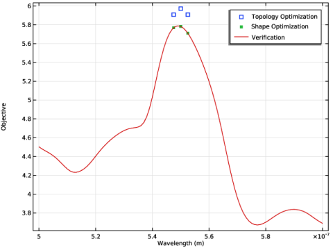
In the Settings window for Global, click Add Expression in the upper-right corner of the y-Axis Data section. From the menu, choose Component 1 (comp1) > Definitions > obj - Objective - V/m.
|
|
3
|
Locate the y-Axis Data section. In the table, enter the following settings:
|
|
4
|
Click to expand the Coloring and Style section. Find the Line style subsection. From the Line list, choose None.
|
|
5
|
|
1
|
|
2
|
|
3
|
|
4
|
Locate the y-Axis Data section. In the table, enter the following settings:
|
|
5
|
|
6
|
|
7
|
Locate the Coloring and Style section. Find the Line markers subsection. From the Marker list, choose Point.
|
|
1
|
|
2
|
|
3
|
|
4
|
Locate the y-Axis Data section. In the table, enter the following settings:
|
|
5
|
Locate the Coloring and Style section. Find the Line style subsection. From the Line list, choose Solid.
|
|
6
|
|
7
|
|
8
|
|
1
|
|
2
|
|
3
|
|
4
|
|
5
|
|
1
|
|
2
|
|
3
|
|
4
|
|
1
|
|
2
|
|
3
|
|
1
|
|
2
|
|
1
|
|
2
|
|
3
|
Clear the Color legend checkbox.
|
|
1
|
|
2
|
|
3
|
|
1
|
|
2
|
|
3
|
|
1
|
|
2
|
|
3
|
|
4
|
|
1
|
|
2
|
|
3
|
|
4
|
|
1
|
|
2
|
|
3
|
|
4
|
Clear the Casts shadows checkbox.
|
|
1
|
|
2
|
|
3
|
Select the Rotate checkbox.
|
|
4
|
|
1
|
|
2
|
|
3
|
|
4
|
|
5
|
|
6
|
|
7
|
|
1
|
|
2
|
|
3
|
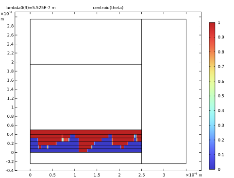
In the Logical expression for inclusion text field, type (0.5<centroid(theta)) && rev1phi<-220/360*pi.
|
|
4
|
|
5
|
|
1
|
|
2
|
|
3
|
|
1
|
|
2
|
|
3
|
|
1
|
|
2
|
|
1
|
|
2
|
|
3
|
|
4
|
|
5
|
Click to expand the Layers section. In the table, enter the following settings:
|
|
6
|
Locate the Selections of Resulting Entities section. Select the Resulting objects selection checkbox.
|
|
1
|
|
2
|
|
3
|
|
4
|
Locate the Selections of Resulting Entities section. Select the Resulting objects selection checkbox.
|
|
1
|
|
2
|
|
3
|
|
4
|
|
5
|
|
6
|
|
1
|
In the Model Builder window, under Component 1 (comp1) > Geometry 1 right-click Rectangle 1 (r1) and choose Duplicate.
|
|
2
|
|
3
|
|
4
|
|
5
|
Locate the Layers section. In the table, enter the following settings:
|
|
1
|
|
2
|
|
3
|
|
4
|
|
5
|
Locate the Selections of Resulting Entities section. Select the Resulting objects selection checkbox.
|
|
1
|
|
2
|
|
3
|
|
4
|
|
5
|
|
6
|
|
1
|
|
2
|
|
3
|
|
4
|
|
5
|
|
1
|
|
2
|
|
1
|
|
2
|
|
3
|
|
4
|
|
5
|
|
6
|
|
7
|
|
1
|
|
2
|
|
3
|
|
4
|
|
5
|
|
1
|
|
2
|
|
3
|
|
4
|
|
1
|
In the Model Builder window, under Component 1 (comp1) > Geometry 1 right-click Source (boxsel3) and choose Duplicate.
|
|
2
|
|
3
|
|
4
|
|
5
|
|
6
|
