
|
|
|


|
8·108 Pa
|
||
|
8·107 Pa
|
||

|
1
|
|
2
|
In the Application Libraries window, select Subsurface Flow Module > Poromechanics > terzaghi_compaction in the tree.
|
|
3
|
Click
|
|
1
|
|
2
|
Go to the Add Physics window.
|
|
3
|
|
4
|
Find the Physics interfaces in study subsection. In the table, clear the Solve checkbox for Study 1.
|
|
5
|
Click the Add to Component 1 button in the window toolbar.
|
|
6
|
|
1
|
|
2
|
Go to the Add Multiphysics window.
|
|
3
|
|
4
|
Find the Multiphysics couplings in study subsection. In the table, clear the Solve checkbox for Study 1.
|
|
5
|
Click the Add to Component button in the window toolbar.
|
|
6
|
|
1
|
|
1
|
|
1
|
In the Model Builder window, under Component 1 (comp1) > Multiphysics click Poroelasticity 1 (poro1).
|
|
2
|
|
3
|
|
1
|
In the Model Builder window, expand the Component 1 (comp1) > Materials node, then click Porous Material 1 (pmat1).
|
|
2
|
|
1
|
|
2
|
|
1
|
In the Model Builder window, expand the Component 1 (comp1) > Definitions node, then click Variables 3.
|
|
2
|
|
1
|
|
2
|
Go to the Add Study window.
|
|
3
|
|
4
|
Click the Add Study button in the window toolbar.
|
|
5
|
|
1
|
|
2
|
|
3
|
Click
|
|
4
|
|
5
|
|
6
|
Click Replace.
|
|
7
|
|
8
|
Click
|
|
9
|
|
10
|
|
11
|
|
12
|
Click Add.
|
|
13
|
|
1
|
|
2
|
In the Settings window for 2D Plot Group, type Hydraulic Head, Poroelasticity in the Label text field.
|
|
3
|
|
1
|
|
2
|
In the Settings window for Surface, click Replace Expression in the upper-right corner of the Expression section. From the menu, choose Component 1 (comp1) > Darcy’s Law > Velocity and pressure > dl.H - Hydraulic head - m.
|
|
1
|
|
2
|
In the Settings window for Contour, click Replace Expression in the upper-right corner of the Expression section. From the menu, choose Component 1 (comp1) > Solid Mechanics > Displacement > solid.disp - Displacement magnitude - m.
|
|
3
|
|
4
|
|
5
|
|
6
|
|
7
|
Clear the Color legend checkbox.
|
|
8
|
|
9
|
|
1
|
|
2
|
|
3
|
|
4
|
|
5
|
|
6
|
Locate the Arrow Positioning section. Find the X grid points subsection. In the Points text field, type 25.
|
|
1
|
|
2
|
|
3
|
|
4
|
|
1
|
|
2
|
Select the Scale factor checkbox.
|
|
3
|
|
1
|
|
2
|
|
3
|
|
4
|
|
5
|
|
6
|
|
7
|
|
8
|
|
1
|
|
2
|
|
1
|
|
2
|
|
3
|
|
1
|
|
2
|
|
3
|
|
1
|
|
2
|
|
3
|
|
4
|
|
5
|
|
6
|
|
7
|
Locate the Coloring and Style section. Find the Point style subsection. From the Color list, choose White.
|
|
8
|
|
9
|
|
1
|
|
2
|
In the Settings window for 2D Plot Group, type Solid-to-Fluid Coupling Term in the Label text field.
|
|
3
|
|
1
|
|
2
|
In the Settings window for Surface, click Replace Expression in the upper-right corner of the Expression section. From the menu, choose Component 1 (comp1) > Definitions > Variables > Q_biot - kg/(m³·s).
|
|
3
|
|
1
|
|
2
|
|
3
|
|
4
|
|
5
|
|
1
|
|
2
|
|
3
|
|
4
|
|
5
|
|
1
|
|
2
|
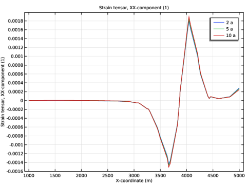
In the Settings window for Line Graph, click Replace Expression in the upper-right corner of the y-Axis Data section. From the menu, choose Component 1 (comp1) > Solid Mechanics > Strain > Strain tensor (material and geometry frames) > solid.eXX - Strain tensor, XX-component.
|
|
3
|
|
4
|
Click Replace Expression in the upper-right corner of the x-Axis Data section. From the menu, choose Component 1 (comp1) > Geometry > Coordinate (material and geometry frames) > X - X-coordinate.
|
|
5
|
|
6
|
|
1
|
|
2
|
|
3
|
In the Settings window for 2D Plot Group, type Hydraulic Head, Poroelasticity, Array in the Label text field.
|
|
4
|
|
5
|
|
6
|
|
7
|
|
1
|
|
2
|
|
3
|
|
4
|
|
5
|
|
1
|
In the Model Builder window, under Results > Hydraulic Head, Poroelasticity, Array click Arrow Surface 1.
|
|
2
|
|
3
|
Select the Manual indexing checkbox.
|
|
1
|
|
2
|
|
3
|
|
4
|
|
5
|
|
1
|
|
2
|
|
3
|
Select the Manual indexing checkbox.
|
|
4
|
|
5
|
|
1
|
|
2
|
|
3
|
|
4
|
|
1
|
In the Model Builder window, expand the Results > Hydraulic Head, Poroelasticity, Array > Contour 1 node, then click Results > Hydraulic Head, Poroelasticity, Array > Contour 3.
|
|
2
|
|
3
|
|
4
|
|
5
|
|
1
|
|
2
|
|
3
|
|
4
|
|
5
|
|
1
|
|
2
|
|
3
|
|
5
|
|
6
|
Clear the Show point checkbox.
|
|
7
|
|
1
|
|
2
|
|
3
|
|
4
|
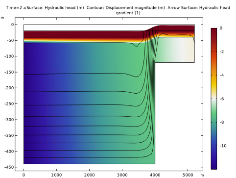
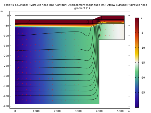
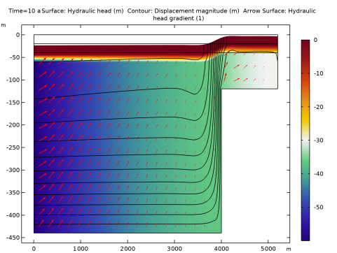
In the Title text area, type Surface: Hydraulic head (m) Contour: Displacement magnitude (m) Arrow Surface: Hydraulic head gradient (1).
|
|
5
|
Clear the Parameter indicator text field.
|
|
6
|
|
7
|
|
1
|
In the Model Builder window, under Results, Ctrl-click to select Pressure (dl), Velocity (dl) 1, von Mises Stress, Hydraulic Head, Poroelasticity, Solid-to-Fluid Coupling Term, Horizontal Strain, and Hydraulic Head, Poroelasticity, Array.
|
|
2
|
Right-click and choose Group.
|
|
1
|
In the Model Builder window, under Results, Ctrl-click to select Hydraulic Head, Velocity (dl), and Compaction.
|
|
2
|
Right-click and choose Group.
|