|
|
|
|
1
|
|
2
|
In the Select Physics tree, select Structural Mechanics > Thermal–Structure Interaction > Thermal Stress, Solid.
|
|
3
|
Click Add.
|
|
4
|
Click
|
|
5
|
|
6
|
Click
|
|
1
|
|
2
|
|
3
|
Click
|
|
4
|
Browse to the model’s Application Libraries folder and double-click the file turbine_stator_parameters.txt.
|
|
1
|
|
2
|
|
3
|
Click
|
|
4
|
Browse to the model’s Application Libraries folder and double-click the file turbine_stator.mphbin.
|
|
5
|
Click
|
|
6
|
|
7
|
|
8
|
|
1
|
|
2
|
In the Geometry Cleanup dialog that opens, click Clean up Automatically to automatically clean up the geometry.
|
|
1
|
|
2
|
|
3
|
|
4
|
|
5
|
|
6
|
|
7
|
|
8
|
|
9
|
|
1
|
|
2
|
|
3
|
|
4
|
Click
|
|
5
|
In the Paste Selection dialog, type 1-5, 9, 11, 14, 16, 17, 21-31, 36-39, 42-56, 63, 65-70, 113, 114-134 in the Selection text field.
|
|
6
|
Click OK.
|
|
1
|
|
2
|
Go to the Add Material window.
|
|
3
|
In the tree, select Material Library > Nickel Alloys > GTD111 DS > GTD111 DS [solid] > GTD111 DS [solid,longitudinal].
|
|
4
|
Click the Add to Component button in the window toolbar.
|
|
5
|
|
1
|
|
3
|
|
1
|
In the Model Builder window, expand the Component 1 (comp1) > Materials > GTD111 DS [solid,longitudinal] (mat1) > Young’s modulus and Poisson’s ratio (Enu) node, then click Piecewise (E_solid_longitudinal_1).
|
|
2
|
|
3
|
|
1
|
In the Model Builder window, under Component 1 (comp1) > Multiphysics click Thermal Expansion 1 (te1).
|
|
2
|
|
3
|
|
1
|
|
2
|
|
3
|
Find the Expression for remaining selection subsection. In the Volume reference temperature text field, type 310[K].
|
|
1
|
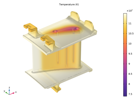
In the Model Builder window, under Component 1 (comp1) > Heat Transfer in Solids (ht) click Initial Values 1.
|
|
2
|
|
3
|
|
1
|
|
2
|
|
3
|
|
4
|
|
5
|
|
6
|
|
1
|
|
2
|
|
3
|
|
4
|
|
5
|
|
6
|
|
1
|
|
3
|
|
4
|
|
5
|
|
6
|
From the list, choose Plate, local transfer coefficient.
|
|
7
|
|
8
|
|
9
|
|
10
|
|
1
|
|
3
|
|
4
|
|
5
|
|
6
|
From the list, choose Plate, local transfer coefficient.
|
|
7
|
|
8
|
|
9
|
|
10
|
|
1
|
|
3
|
|
4
|
|
5
|
|
6
|
From the list, choose Plate, local transfer coefficient.
|
|
7
|
|
8
|
|
9
|
|
10
|
|
1
|
|
3
|
|
4
|
From the list, choose Diagonal.
|
|
5
|
|
1
|
|
3
|
|
4
|
From the list, choose Diagonal.
|
|
5
|
|
1
|
|
3
|
|
4
|
From the list, choose Diagonal.
|
|
5
|
|
1
|
|
2
|
Click the Custom button.
|
|
3
|
|
4
|
|
5
|
|
6
|
|
1
|
|
2
|
|
3
|
|
4
|
|
5
|
|
6
|
Locate the Element Size Parameters section.
|
|
7
|
|
8
|
|
1
|
|
2
|
|
1
|
|
2
|
|
3
|
In the Model Builder window, expand the Study 1 > Solver Configurations > Solution 1 (sol1) > Stationary Solver 1 node, then click Segregated 1.
|
|
4
|
|
5
|
|
6
|
In the Model Builder window, expand the Study 1 > Solver Configurations > Solution 1 (sol1) > Stationary Solver 1 > Segregated 1 node, then click Temperature.
|
|
7
|
|
8
|
|
9
|
|
10
|
In the Model Builder window, under Study 1 > Solver Configurations > Solution 1 (sol1) > Stationary Solver 1 > Segregated 1 click Solid Mechanics.
|
|
11
|
|
12
|
|
13
|
|
14
|
|
1
|
|
2
|
|
3
|
|
1
|
|
2
|
|
1
|
|
2
|
|
3
|
|
4
|
|
5
|
|
6
|
Select the Show frame checkbox.
|
|
1
|
|
2
|
|
3
|
|
4
|
|
5
|
|
1
|
|
2
|
|
3
|
Clear the Plot dataset edges checkbox.
|
|
1
|
|
2
|
|
3
|
|
4
|
|
5
|
|
6
|
|
7
|
|
1
|
|
2
|
|
1
|
|
2
|
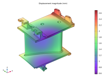
In the Settings window for Surface, click Replace Expression in the upper-right corner of the Expression section. From the menu, choose Component 1 (comp1) > Solid Mechanics > Displacement > solid.disp - Displacement magnitude - m.
|
|
3
|
|
4
|
|
5
|
|
6
|