|
|
|
|
•
|
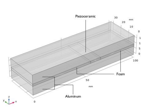
Solid Mechanics: the cantilever beam is fixed at its surfaces at x = 0; all other surfaces are free.
|
|
•
|
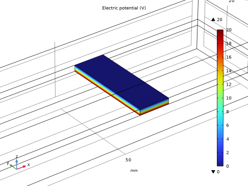
Electrostatics: The system applies a 20 V potential difference between the top and bottom surfaces of the piezoceramic domain (Figure 2). This gives rise to an electric field perpendicular to the poling direction (x direction) and thus induces a transverse shear strain.
 |
|
1
|
|
2
|
In the Select Physics tree, select Structural Mechanics > Electromagnetics–Structure Interaction > Piezoelectricity > Piezoelectricity, Solid.
|
|
3
|
Click Add.
|
|
4
|
Click
|
|
5
|
|
6
|
Click
|
|
1
|
|
2
|
|
3
|
|
1
|
|
2
|
|
3
|
|
4
|
|
5
|
|
6
|
Click
|
|
1
|
|
2
|
|
3
|
|
4
|
|
5
|
|
6
|
|
7
|
|
8
|
Clear the Bottom checkbox.
|
|
10
|
Click
|
|
11
|
|
12
|
|
13
|
|
1
|
|
2
|
|
4
|
|
1
|
|
2
|
|
3
|
Click
|
|
1
|
In the Model Builder window, under Component 1 (comp1) > Solid Mechanics (solid) click Piezoelectric Material 1.
|
|
2
|
|
3
|
Click
|
|
5
|
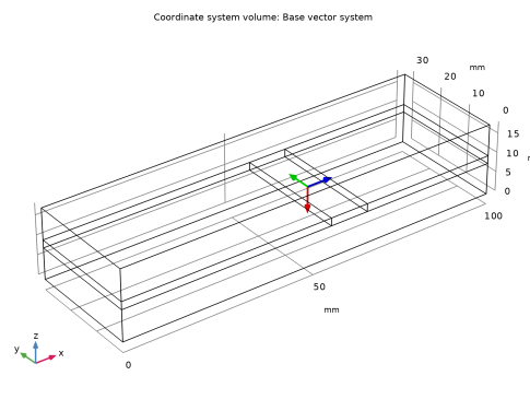
Locate the Coordinate System Selection section. From the Coordinate system list, choose Base Vector System 2 (sys2).
|
|
1
|
|
2
|
Go to the Add Material window.
|
|
3
|
|
4
|
Click the Add to Component button in the window toolbar.
|
|
1
|
|
2
|
Click
|
|
1
|
|
2
|
|
4
|
Locate the Material Contents section. In the table, enter the following settings:
|
|
1
|
Go to the Add Material window.
|
|
2
|
|
3
|
Click the Add to Component button in the window toolbar.
|
|
1
|
|
1
|
|
2
|
|
1
|
|
3
|
|
4
|
|
1
|
|
1
|
|
2
|
|
1
|
|
2
|
|
3
|
|
4
|
Click
|
|
5
|
|
6
|
|
1
|
|
1
|
|
2
|
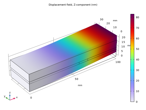
In the Settings window for Volume, click Replace Expression in the upper-right corner of the Expression section. From the menu, choose Component 1 (comp1) > Solid Mechanics > Displacement > Displacement field - m > w - Displacement field, Z-component.
|
|
3
|
|
4
|
|
5
|
|
1
|
In the Model Builder window, under Results > Electric Potential (es), Ctrl-click to select Multislice 1 and Streamline Multislice 1.
|
|
2
|
Right-click and choose Delete.
|
|
1
|
|
2
|
In the Settings window for Surface, click Replace Expression in the upper-right corner of the Expression section. From the menu, choose Component 1 (comp1) > Electrostatics > Electric > V - Electric potential - V.
|
|
3
|
|
4
|
|
5
|
|
1
|
|
2
|
|
1
|
|
2
|
|
3
|
|
4
|
Locate the Positioning section. Find the x grid points subsection. From the Entry method list, choose Coordinates.
|
|
5
|
|
6
|
|
7
|
|
8
|