|
|
|
|
•
|
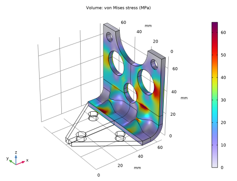
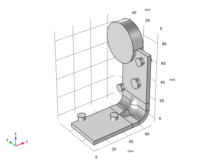
When exposed to a peak acceleration of 4g in all three global directions simultaneously, the equivalent stress is not allowed to exceed 80 MPa anywhere. This criterion is nondifferentiable, because the location of the peak stress can jump from one place to another. A gradient-free optimization algorithm must thus be used.
|
|
•
|

|
1
|
|
2
|
|
3
|
Click Add.
|
|
4
|
Click
|
|
5
|
|
6
|
Click
|
|
1
|
|
2
|
|
3
|
Click
|
|
4
|
Browse to the model’s Application Libraries folder and double-click the file multistudy_bracket_optimization_parameters.txt.
|
|
1
|
|
2
|
|
3
|
|
4
|
|
5
|
Select the Design Module Boolean operations checkbox.
|
|
6
|
|
7
|
Browse to the model’s Application Libraries folder and double-click the file multistudy_bracket_optimization_geom_sequence.mph.
|
|
8
|
|
1
|
|
2
|
Go to the Add Material window.
|
|
3
|
|
4
|
Click the Add to Component button in the window toolbar.
|
|
5
|
|
1
|
|
2
|
|
1
|
|
2
|
In the Settings window for Rigid Connector, type Rigid Connector (Mounted Component) in the Label text field.
|
|
4
|
|
5
|
|
1
|
|
2
|
In the Settings window for Mass and Moment of Inertia, locate the Mass and Moment of Inertia section.
|
|
3
|
|
4
|
From the list, choose Diagonal.
|
|
5
|
Specify the I matrix as
|
|
1
|
|
1
|
|
2
|
|
3
|
|
1
|
|
2
|
|
3
|
|
4
|
|
6
|
Click
|
|
1
|
|
2
|
|
3
|
|
4
|
Click
|
|
1
|
|
2
|
|
1
|
|
2
|
|
3
|
|
4
|
|
1
|
|
2
|
|
3
|
|
4
|
|
1
|
|
2
|
In the Settings window for Applied Force, type Force 4g on Mounted Component in the Label text field.
|
|
3
|
|
1
|
|
2
|
Go to the Add Study window.
|
|
3
|
|
4
|
Click the Add Study button in the window toolbar.
|
|
5
|
|
1
|
|
2
|
|
3
|
|
4
|
|
1
|
|
2
|
|
1
|
|
2
|
|
3
|
|
4
|
Click Replace Expression in the upper-right corner of the Expression section. From the menu, choose Component 1 (comp1) > Solid Mechanics > Material properties > solid.rho - Density - kg/m³.
|
|
1
|
|
2
|
|
3
|
|
4
|
|
5
|
Click Replace Expression in the upper-right corner of the Expression section. From the menu, choose Component 1 (comp1) > Solid Mechanics > Stress > solid.mises - von Mises stress - N/m².
|
|
1
|
|
2
|
|
1
|
|
2
|
|
3
|
|
1
|
|
2
|
|
1
|
|
2
|
|
3
|
|
4
|
|
1
|
|
2
|
Go to the Add Study window.
|
|
3
|
|
4
|
Click the Add Study button in the window toolbar.
|
|
5
|
|
1
|
|
2
|
|
3
|
|
1
|
|
2
|
|
3
|
|
1
|
|
2
|
|
3
|
|
4
|
|
5
|
Click Replace Expression in the upper-right corner of the Objective Function section. From the menu, choose Component 1 (comp1) > Definitions > comp1.mass - Domain Probe 1 - kg.
|
|
6
|
Locate the Objective Function section. In the table, enter the following settings:
|
|
7
|
|
8
|
|
9
|
Browse to the model’s Application Libraries folder and double-click the file multistudy_bracket_optimization_ctrlvars.txt.
|
|
10
|
Locate the Constraints section. In the table, enter the following settings:
|
|
11
|
|
12
|
|
13
|
|
1
|
|
2
|
Click
|
|
1
|
In the Model Builder window, expand the Results > Tables node, then click Results > Stress in Optimized Region.
|
|
2
|
|
1
|
|
2
|
|
3
|
Click
|
|
4
|
Browse to the model’s Application Libraries folder and double-click the file multistudy_bracket_optimization_geom_sequence_parameters.txt.
|
|
1
|
|
2
|
|
3
|
|
4
|
|
5
|
|
6
|
Select the Design Module Boolean operations checkbox.
|
|
1
|
|
2
|
|
3
|
|
4
|
|
5
|
Click
|
|
1
|
|
2
|
|
3
|
In the xw text field, type if((abs(s-0.5)<wInd/lY),dInd/2*(1+cos(pi*lY/if(wInd>4[mm],wInd,4[mm])*(s-0.5))),0).
|
|
4
|
|
5
|
Click
|
|
1
|
|
2
|
Select the object pc1 only.
|
|
3
|
|
4
|
|
1
|
|
2
|
|
3
|
|
4
|
|
5
|
|
1
|
|
2
|
Select the object ls1 only.
|
|
3
|
|
4
|
|
1
|
|
2
|
Click in the Graphics window and then press Ctrl+A to select all objects.
|
|
3
|
|
1
|
|
2
|
|
3
|
Click the Angles button.
|
|
4
|
|
5
|
|
6
|
|
7
|
|
8
|
|
9
|
Click
|
|
1
|
|
2
|
|
3
|
|
4
|
|
5
|
|
6
|
Click
|
|
1
|
|
2
|
|
3
|
Clear the Unite with input objects checkbox.
|
|
4
|
Click to expand the Start Profile section. Click to select the
|
|
5
|
On the object rev1, select Boundary 1 only.
|
|
6
|
Click to expand the End Profile section. Click to select the
|
|
7
|
On the object blk1, select Boundary 5 only.
|
|
8
|
|
1
|
|
2
|
Select the object loft1 only.
|
|
3
|
|
4
|
Select the Keep input objects checkbox.
|
|
5
|
|
6
|
|
7
|
|
8
|
Click
|
|
1
|
|
2
|
|
3
|
|
4
|
|
5
|
|
6
|
|
7
|
|
8
|
|
1
|
|
2
|
In the Settings window for Cylinder, locate the Size and Shape, Position, and Axis sections and type the following settings for the six newly created nodes.
|
|
3
|
|
1
|
|
2
|
|
3
|
|
4
|
|
5
|
Click
|
|
1
|
|
2
|
|
3
|
|
4
|
|
5
|
|
6
|
|
1
|
In the Model Builder window, under Component 1 (comp1) > Geometry 1 right-click Work Plane 2 (wp2) and choose Extrude.
|
|
2
|
|
4
|
Click
|
|
1
|
|
2
|
|
3
|
|
4
|
|
5
|
|
6
|
|
1
|
|
2
|
|
3
|
Select the Keep input objects checkbox.
|
|
4
|
|
5
|
|
6
|
|
7
|
Select the object dif1 only.
|
|
8
|
Click
|
|
9
|