
|
|
|
|
•
|
|
•
|
|
1
|
|
2
|
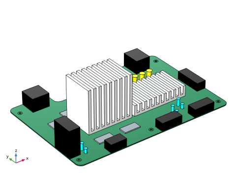
In the Application Libraries window, select Structural Mechanics Module > Dynamics and Vibration > motherboard_shock_response in the tree.
|
|
3
|
Click
|
|
1
|
In the Model Builder window, under Global Definitions, Ctrl-click to select Acceleration (g) vs. Frequency (Hz) (int1) and Vertical Spectrum (vsp).
|
|
2
|
Right-click and choose Delete.
|
|
1
|
In the Model Builder window, under Results > Datasets, Ctrl-click to select Grid 1D 1 and Study 1/Solution 1 (sol1).
|
|
2
|
Right-click and choose Delete.
|
|
1
|
|
2
|
|
3
|
Click
|
|
4
|
Browse to the model’s Application Libraries folder and double-click the file motherboard_random_vibration_parameters.txt.
|
|
1
|
|
2
|
|
3
|
|
4
|
|
1
|
|
2
|
|
3
|
|
1
|
|
2
|
|
3
|
|
1
|
|
2
|
|
3
|
|
1
|
|
2
|
|
3
|
|
1
|
|
2
|
|
3
|
|
1
|
|
2
|
|
1
|
|
2
|
|
3
|
|
4
|
Locate the Prescribed Displacement at Center of Rotation section. Select the Prescribed in x direction checkbox.
|
|
5
|
Select the Prescribed in y direction checkbox.
|
|
6
|
Select the Prescribed in z direction checkbox.
|
|
7
|
|
8
|
Select the Constrain rotation around x-axis checkbox.
|
|
9
|
Select the Constrain rotation around y-axis checkbox.
|
|
10
|
Select the Constrain rotation around z-axis checkbox.
|
|
11
|
|
1
|
|
2
|
|
3
|
|
1
|
|
2
|
|
3
|
|
1
|
|
2
|
|
3
|
|
1
|
|
2
|
|
3
|
|
1
|
|
2
|
|
3
|
|
1
|
|
2
|
|
3
|
|
4
|
|
5
|
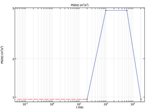
Find the Rectangle search region subsection. In the Smallest real part (Eigenfrequency) text field, type fL/2.
|
|
6
|
|
7
|
|
8
|
|
9
|
|
1
|
|
2
|
In the Settings window for Global Evaluation, type Relative Modal Mass Contribution in the Label text field.
|
|
3
|
Locate the Expressions section. In the table, enter the following settings:
|
|
4
|
Click
|
|
1
|
Go to the Table 2 window.
|
|
2
|
Click the Table Graph button in the window toolbar.
|
|
1
|
|
2
|
|
3
|
|
4
|
|
5
|
|
6
|
|
1
|
|
2
|
|
3
|
Locate the Plot Settings section.
|
|
4
|
|
5
|
|
6
|
|
1
|
|
2
|
|
4
|
Locate the y-Coordinates section. In the table, enter the following settings:
|
|
5
|
|
6
|
|
7
|
|
8
|
|
10
|
|
11
|
|
12
|
|
1
|
|
2
|
Go to the Add Study window.
|
|
3
|
|
4
|
Right-click and choose Add Study.
|
|
5
|
|
1
|
|
2
|
|
3
|
|
4
|
|
5
|
|
6
|
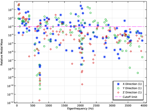
In the Excluded if text field, type comp1.rsp1.mEffLX+comp1.rsp1.mEffLY+comp1.rsp1.mEffLZ<comp1.rsp1.mass*1e-4.
|
|
7
|
|
1
|
|
2
|
Go to the Add Study window.
|
|
3
|
Find the Studies subsection. In the Select Study tree, select Preset Studies for Selected Physics Interfaces > Random Vibration (PSD).
|
|
4
|
Right-click and choose Add Study.
|
|
5
|
|
1
|
|
2
|
|
3
|
|
1
|
|
2
|
|
3
|
|
5
|
|
6
|
In the Argument table, enter the following settings:
|
|
7
|
Click to expand the Data Transformation for Interpolation section. From the Argument list, choose Logarithmic.
|
|
8
|
|
9
|
Click
|
|
1
|
|
2
|
|
3
|
|
1
|
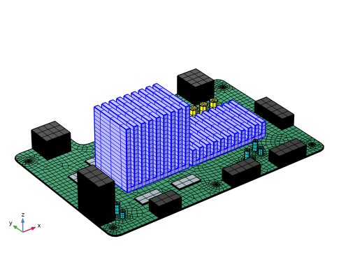
In the Model Builder window, expand the Global Definitions > Reduced-Order Modeling node, then click Global Reduced-Model Inputs 1.
|
|
2
|
|
1
|
In the Model Builder window, under Component 1 (comp1) > Solid Mechanics (solid) click Base Excitation 1.
|
|
2
|
|
3
|
|
1
|
|
2
|
|
3
|
|
4
|
|
5
|
|
6
|
|
7
|
|
1
|
|
2
|
|
3
|
Select the Modify model configuration for study step checkbox.
|
|
4
|
In the tree, select Component 1 (comp1) > Solid Mechanics (solid) > Linear Elastic Material 1 > Damping 1.
|
|
5
|
Right-click and choose Disable.
|
|
1
|
In the Model Builder window, under Global Definitions > Reduced-Order Modeling click Random Vibration 1 (rvib1).
|
|
2
|
|
3
|
Locate the Power Spectrum section. In the table, enter the following settings:
|
|
4
|
|
5
|
|
6
|
|
7
|
|
1
|
|
2
|
|
3
|
Select the Only plot when requested checkbox.
|
|
4
|
|
1
|
|
2
|
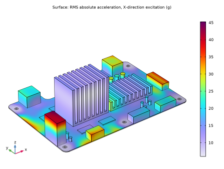
In the Settings window for 3D Plot Group, type RMS absolute acceleration X-excitation in the Label text field.
|
|
3
|
|
4
|
|
5
|
|
6
|
Click to expand the Selection section.
|
|
1
|
|
2
|
|
3
|
|
4
|
|
5
|
|
6
|
|
7
|
|
1
|
In the Model Builder window, under Global Definitions > Reduced-Order Modeling right-click Random Vibration, X (rvib1) and choose Duplicate.
|
|
2
|
|
3
|
Locate the Power Spectrum section. In the table, enter the following settings:
|
|
1
|
|
2
|
|
3
|
Locate the Power Spectrum section. In the table, enter the following settings:
|
|
1
|
|
2
|
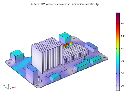
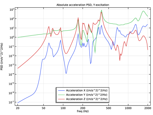
In the Settings window for 3D Plot Group, type RMS absolute acceleration Y-excitation in the Label text field.
|
|
3
|
Locate the Title section. In the Title text area, type Surface: RMS absolute acceleration, Y-direction excitation (g).
|
|
1
|
In the Model Builder window, expand the RMS absolute acceleration Y-excitation node, then click Surface 1.
|
|
2
|
|
3
|
|
4
|
|
1
|
In the Model Builder window, right-click RMS absolute acceleration Y-excitation and choose Duplicate.
|
|
2
|
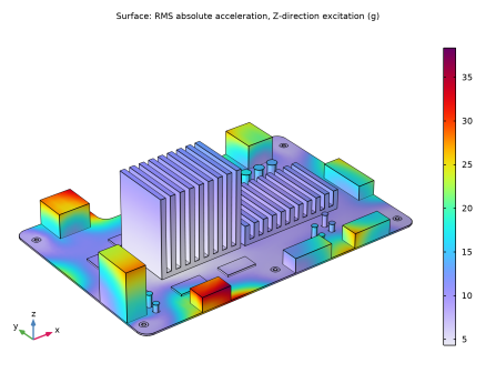
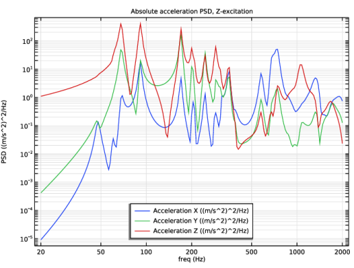
In the Settings window for 3D Plot Group, type RMS absolute acceleration Z-excitation in the Label text field.
|
|
3
|
Locate the Title section. In the Title text area, type Surface: RMS absolute acceleration, Z-direction excitation (g).
|
|
1
|
In the Model Builder window, expand the RMS absolute acceleration Z-excitation node, then click Surface 1.
|
|
2
|
|
3
|
|
4
|
|
1
|
|
2
|
|
3
|
|
5
|
|
1
|
|
2
|
|
1
|
|
2
|
In the Settings window for Global Evaluation Sweep, type Global Evaluation Sweep, X-excitation Acceleration PSD in the Label text field.
|
|
3
|
|
4
|
Locate the Parameters section. In the table, enter the following settings:
|
|
5
|
Locate the Expressions section. In the table, enter the following settings:
|
|
6
|
Click
|
|
1
|
Go to the Table 3 window.
|
|
2
|
Click the Table Graph button in the window toolbar.
|
|
1
|
|
2
|
Select the Show legends checkbox.
|
|
3
|
|
4
|
|
1
|
|
2
|
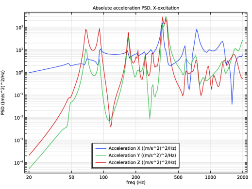
In the Settings window for 1D Plot Group, type Absolute acceleration PSD X-excitation in the Label text field.
|
|
3
|
Locate the Plot Settings section.
|
|
4
|
|
5
|
|
6
|
|
7
|
|
8
|
|
1
|
In the Model Builder window, right-click Global Evaluation Sweep, X-excitation Acceleration PSD and choose Duplicate.
|
|
2
|
In the Settings window for Global Evaluation Sweep, type Global Evaluation Sweep, Y-excitation Acceleration PSD in the Label text field.
|
|
3
|
Locate the Expressions section. In the table, enter the following settings:
|
|
4
|
|
1
|
In the Model Builder window, right-click Absolute acceleration PSD X-excitation and choose Duplicate.
|
|
2
|
|
3
|
In the Settings window for 1D Plot Group, type Absolute acceleration PSD Y-excitation in the Label text field.
|
|
4
|
|
1
|
|
2
|
|
3
|
|
4
|
|
1
|
In the Model Builder window, right-click Global Evaluation Sweep, Y-excitation Acceleration PSD and choose Duplicate.
|
|
2
|
In the Settings window for Global Evaluation Sweep, type Global Evaluation Sweep, Z-excitation Acceleration PSD in the Label text field.
|
|
3
|
Locate the Expressions section. In the table, enter the following settings:
|
|
4
|
|
1
|
In the Model Builder window, right-click Absolute acceleration PSD Y-excitation and choose Duplicate.
|
|
2
|
|
3
|
In the Settings window for 1D Plot Group, type Absolute acceleration PSD Z-excitation in the Label text field.
|
|
4
|
|
1
|
|
2
|
|
3
|
|
4
|
|
1
|
|
2
|
In the Settings window for Global Evaluation, type Bolt Forces X-excitation in the Label text field.
|
|
3
|
|
4
|
|
5
|
Browse to the model’s Application Libraries folder and double-click the file motherboard_random_vibration_bolt_forcesX.txt.
|
|
6
|
Click
|
|
1
|
|
2
|
In the Settings window for Global Evaluation, type Bolt Forces Y-excitation in the Label text field.
|
|
3
|
|
4
|
|
5
|
Browse to the model’s Application Libraries folder and double-click the file motherboard_random_vibration_bolt_forcesY.txt.
|
|
6
|
Click
|
|
1
|
|
2
|
In the Settings window for Global Evaluation, type Bolt Forces Z-excitation in the Label text field.
|
|
3
|
|
4
|
|
5
|
Browse to the model’s Application Libraries folder and double-click the file motherboard_random_vibration_bolt_forcesZ.txt.
|
|
6
|
Click
|