|
|
|

|
•
|
|
•
|
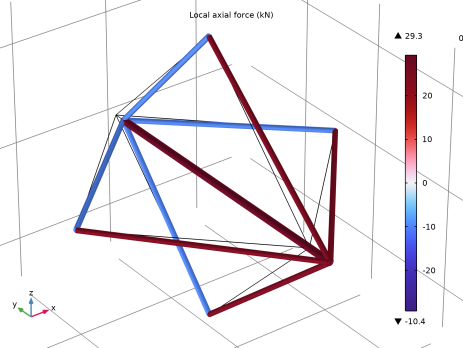
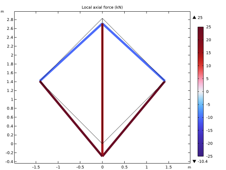
The truss members have a circular cross section with a radius of 0.05 m. In the 3D case, the area of the central bar is doubled.
|
|
-5.14·10-4 m
|
-5.15·10-4 m
|
|
|
-2.13·10-4 m
|
-2.13·10-4 m
|
|
|
1
|
|
2
|
|
3
|
Click Add.
|
|
4
|
Click
|
|
5
|
|
6
|
Click
|
|
1
|
|
2
|
|
3
|
|
4
|
|
5
|
|
6
|
Click
|
|
7
|
|
1
|
|
2
|
|
3
|
|
4
|
|
5
|
|
6
|
Click
|
|
1
|
|
2
|
|
3
|
|
4
|
|
1
|
|
1
|
|
3
|
|
4
|
|
1
|
In the Model Builder window, under Global Definitions right-click Materials and choose Blank Material.
|
|
2
|
|
3
|
|
4
|
Click
|
|
5
|
In the Material properties tree, select Solid Mechanics > Linear Elastic Material > Young’s Modulus and Poisson’s Ratio.
|
|
6
|
Click
|
|
7
|
Locate the Material Contents section. In the table, enter the following settings:
|
|
1
|
|
2
|
Go to the Result Templates window.
|
|
3
|
|
4
|
Click the Add Result Template button in the window toolbar.
|
|
5
|
|
1
|
|
2
|
|
3
|
Select the Show maximum and minimum values checkbox.
|
|
1
|
|
2
|
|
3
|
|
4
|
|
1
|
|
2
|
In the Settings window for Evaluation Group, type Displacement of Vertices (2D) in the Label text field.
|
|
1
|
|
3
|
|
5
|
|
1
|
|
2
|
|
3
|
|
1
|
|
2
|
|
3
|
|
1
|
|
2
|
|
3
|
|
1
|
|
2
|
|
1
|
|
2
|
|
1
|
|
2
|
In the Settings window for Evaluation Group, type Axial Force in Members (2D) in the Label text field.
|
|
1
|
|
2
|
|
4
|
|
1
|
|
2
|
Go to the Add Physics window.
|
|
3
|
|
4
|
Find the Physics interfaces in study subsection. In the table, clear the Solve checkbox for Study 1.
|
|
5
|
Click the Add to Component 2 button in the window toolbar.
|
|
6
|
|
1
|
|
2
|
Go to the Add Study window.
|
|
3
|
|
4
|
Find the Physics interfaces in study subsection. In the table, clear the Solve checkbox for Truss (truss).
|
|
5
|
Click the Add Study button in the window toolbar.
|
|
6
|
|
1
|
|
2
|
|
3
|
|
1
|
|
2
|
|
3
|
|
4
|
|
5
|
|
6
|
|
1
|
|
2
|
|
3
|
Select the Keep input objects checkbox.
|
|
4
|
Select the object wp1 only.
|
|
5
|
|
6
|
|
7
|
|
8
|
|
9
|
Click
|
|
1
|
|
2
|
|
3
|
|
4
|
|
5
|
|
6
|
Click
|
|
1
|
|
2
|
|
3
|
|
1
|
|
2
|
|
3
|
|
1
|
|
2
|
|
3
|
|
1
|
|
2
|
|
1
|
In the Model Builder window, under Component 2 (comp2) > Truss 2 (truss2) click Cross-Section Data 1.
|
|
2
|
|
3
|
|
1
|
|
3
|
|
4
|
|
1
|
|
1
|
|
3
|
|
4
|
|
1
|
|
2
|
Go to the Result Templates window.
|
|
3
|
|
4
|
Click the Add Result Template button in the window toolbar.
|
|
5
|
|
1
|
|
2
|
|
3
|
Select the Show maximum and minimum values checkbox.
|
|
1
|
|
2
|
|
3
|
|
1
|
|
2
|
In the Settings window for Evaluation Group, type Displacement of Vertices (3D) in the Label text field.
|
|
3
|
|
1
|
In the Model Builder window, expand the Displacement of Vertices (3D) node, then click Point Evaluation 1.
|
|
3
|
|
5
|
|
1
|
|
2
|
In the Settings window for Evaluation Group, type Axial Force in Members (3D) in the Label text field.
|
|
3
|
|
1
|
In the Model Builder window, expand the Axial Force in Members (3D) node, then click Global Evaluation 1.
|
|
2
|
|
4
|