|
|
|
|
1
|
|
2
|
|
3
|
Click Add.
|
|
4
|
Click
|
|
5
|
|
6
|
Click
|
|
1
|
|
2
|
|
1
|
|
2
|
|
3
|
Click
|
|
4
|
Browse to the model’s Application Libraries folder and double-click the file hinge_assembly.mphbin.
|
|
5
|
Click
|
|
1
|
|
2
|
|
3
|
|
4
|
Clear the Create pairs checkbox.
|
|
5
|
Click
|
|
1
|
|
2
|
Go to the Add Material window.
|
|
3
|
|
4
|
Click the Add to Component button in the window toolbar.
|
|
5
|
|
1
|
|
1
|
|
3
|
In the Settings window for Rigid Connector, locate the Prescribed Displacement at Center of Rotation section.
|
|
4
|
Select the Prescribed in x direction checkbox.
|
|
1
|
|
2
|
|
3
|
Select the Offset checkbox.
|
|
4
|
|
5
|
|
1
|
|
1
|
|
3
|
In the Settings window for Rigid Connector, locate the Prescribed Displacement at Center of Rotation section.
|
|
4
|
Select the Prescribed in x direction checkbox.
|
|
5
|
|
6
|
Select the Prescribed in y direction checkbox.
|
|
7
|
|
8
|
Select the Prescribed in z direction checkbox.
|
|
9
|
|
10
|
|
11
|
In the Show More Options dialog, in the tree, select the checkbox for the node Physics > Equation Contributions.
|
|
12
|
Click OK.
|
|
1
|
|
2
|
|
3
|
|
1
|
|
2
|
|
3
|
|
1
|
|
2
|
|
3
|
|
5
|
|
6
|
Locate the Element Size Parameters section.
|
|
7
|
|
1
|
|
2
|
|
3
|
|
4
|
Click
|
|
1
|
|
2
|
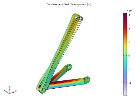
In the Settings window for Volume, click Replace Expression in the upper-right corner of the Expression section. From the menu, choose Component 1 (comp1) > Solid Mechanics > Displacement > Displacement field - m > u - Displacement field, X-component.
|
|
3
|
|
1
|
|
2
|