
|
|
|
|
•
|
|
•
|
|
•
|
|
•
|
|
•
|
|
•
|
|
•
|
|
•
|
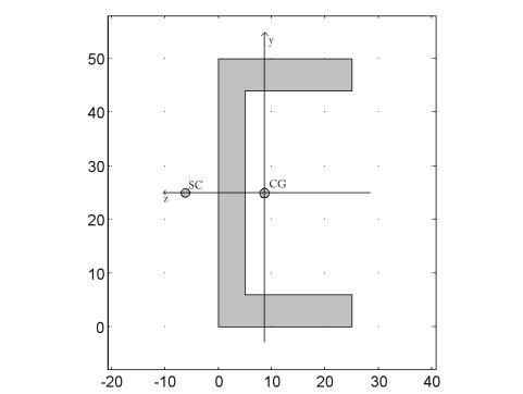
Locations for axial stress evaluation are positioned at the outermost corners of the profile at the points
(y1, z1)=(−0.025, −0.0164) (y2, z2)=(0.025, −0.0164) (y3, z3)=(0.025, 0.0086), (y4, z4)=(−0.025, 0.0086) measured in the local coordinate system. The indices of the coordinates are point identifiers. |
|
•
|
|
•
|
|
•
|
|
•
|
|
•
|
|
•
|


|
1
|
|
2
|
|
3
|
Click Add.
|
|
4
|
Click
|
|
5
|
|
6
|
Click
|
|
1
|
|
2
|
|
1
|
In the Model Builder window, right-click Global Definitions and choose Load and Constraint Groups > Load Group.
|
|
2
|
|
3
|
|
1
|
|
2
|
|
3
|
|
1
|
|
2
|
|
4
|
Click
|
|
1
|
In the Model Builder window, under Component 1 (comp1) right-click Materials and choose Blank Material.
|
|
2
|
|
1
|
In the Model Builder window, under Component 1 (comp1) right-click Definitions and choose Variables.
|
|
2
|
|
m4
|
|||
|
m4
|
|||
|
m4
|
|||
|
1
|
|
2
|
|
3
|
Locate the Definition section. In the Expression text field, type -FZ*L*y/comp1.Izz+FY*L*z/comp1.Iyy.
|
|
4
|
|
5
|
Locate the Plot Parameters section. In the table, enter the following settings:
|
|
6
|
Locate the Units section. In the table, enter the following settings:
|
|
7
|
|
8
|
|
1
|
|
2
|
|
1
|
|
2
|
|
3
|
|
4
|
|
5
|
|
6
|
|
7
|
|
1
|
|
2
|
|
3
|
|
4
|
Specify the V vector as
|
|
1
|
|
2
|
|
1
|
|
1
|
|
3
|
|
4
|
|
5
|
|
6
|
|
1
|
|
2
|
|
3
|
Select the Define load cases checkbox.
|
|
4
|
Click
|
|
6
|
|
7
|
|
8
|
|
1
|
|
2
|
|
3
|
Select the Apply conversions to expressions with the same dimensions checkbox.
|
|
4
|
Click
|
|
5
|
|
6
|
|
7
|
Click OK.
|
|
8
|
|
10
|
Click
|
|
1
|
|
2
|
|
3
|
|
4
|
|
1
|
|
2
|
In the Settings window for Point Evaluation, type Case1: Displacement/Rotation in the Label text field.
|
|
3
|
|
5
|
Click Replace Expression in the upper-right corner of the Expressions section. From the menu, choose Component 1 (comp1) > Beam > Displacement > Displacement field - m > u - Displacement field, X-component.
|
|
6
|
Click Add Expression in the upper-right corner of the Expressions section. From the menu, choose Component 1 (comp1) > Definitions > Variables > deltaX - X displacement - m.
|
|
7
|
Click Add Expression in the upper-right corner of the Expressions section. From the menu, choose Component 1 (comp1) > Beam > Displacement > Displacement field - m > v - Displacement field, Y-component.
|
|
8
|
Click Add Expression in the upper-right corner of the Expressions section. From the menu, choose Component 1 (comp1) > Definitions > Variables > deltaY - Y displacement - m.
|
|
9
|
Click Add Expression in the upper-right corner of the Expressions section. From the menu, choose Component 1 (comp1) > Beam > Displacement > Displacement field - m > w - Displacement field, Z-component.
|
|
10
|
Click Add Expression in the upper-right corner of the Expressions section. From the menu, choose Component 1 (comp1) > Definitions > Variables > deltaZ - Z displacement - m.
|
|
11
|
Click Add Expression in the upper-right corner of the Expressions section. From the menu, choose Component 1 (comp1) > Beam > Displacement > Rotation field - rad > thx - Rotation field, X-component.
|
|
12
|
Click Add Expression in the upper-right corner of the Expressions section. From the menu, choose Component 1 (comp1) > Definitions > Variables > thetaX - Twist - 1.
|
|
13
|
Locate the Expressions section. In the table, enter the following settings:
|
|
14
|
Click
|
|
1
|
|
2
|
|
1
|
|
2
|
In the Settings window for Point Evaluation, type Case2: Displacement/Rotation in the Label text field.
|
|
4
|
|
5
|
Click Replace Expression in the upper-right corner of the Expressions section. From the menu, choose Component 1 (comp1) > Beam > Displacement > Displacement field - m > w - Displacement field, Z-component.
|
|
6
|
Click Add Expression in the upper-right corner of the Expressions section. From the menu, choose Component 1 (comp1) > Definitions > Variables > deltaZ_g - Z displacement due to gravity load - m.
|
|
7
|
Click Add Expression in the upper-right corner of the Expressions section. From the menu, choose Component 1 (comp1) > Beam > Displacement > Rotation field - rad > thx - Rotation field, X-component.
|
|
8
|
Click Add Expression in the upper-right corner of the Expressions section. From the menu, choose Component 1 (comp1) > Definitions > Variables > thetaX_g - Twist due to gravity load - 1.
|
|
9
|
Locate the Expressions section. In the table, enter the following settings:
|
|
10
|
Click
|
|
1
|
|
2
|
|
1
|
|
3
|
|
4
|
|
5
|
|
6
|
Click Replace Expression in the upper-right corner of the Expressions section. From the menu, choose Component 1 (comp1) > Beam > Stress > Stress variables at first evaluation point > beam.s1 - Normal stress at first evaluation point - N/m².
|
|
7
|
Click Add Expression in the upper-right corner of the Expressions section. From the menu, choose Component 1 (comp1) > Beam > Stress > Stress variables at second evaluation point > beam.s2 - Normal stress at second evaluation point - N/m².
|
|
8
|
Click Add Expression in the upper-right corner of the Expressions section. From the menu, choose Component 1 (comp1) > Beam > Stress > Stress variables at third evaluation point > beam.s3 - Normal stress at third evaluation point - N/m².
|
|
9
|
Click Add Expression in the upper-right corner of the Expressions section. From the menu, choose Component 1 (comp1) > Beam > Stress > Stress variables at fourth evaluation point > beam.s4 - Normal stress at fourth evaluation point - N/m².
|
|
10
|
Locate the Expressions section. In the table, enter the following settings:
|
|
11
|
Click
|
|
1
|
|
2
|
|
1
|
|
2
|
|
3
|
|
5
|
Click Replace Expression in the upper-right corner of the Expressions section. From the menu, choose Component 1 (comp1) > Beam > Stress > Stress variables at first evaluation point > beam.sb1 - Bending stress at first evaluation point - N/m².
|
|
6
|
Click Add Expression in the upper-right corner of the Expressions section. From the menu, choose Component 1 (comp1) > Definitions > Functions > sigmabx(y, z) - sigmabx.
|
|
7
|
Click Add Expression in the upper-right corner of the Expressions section. From the menu, choose Component 1 (comp1) > Beam > Stress > Stress variables at second evaluation point > beam.sb2 - Bending stress at second evaluation point - N/m².
|
|
8
|
Click Add Expression in the upper-right corner of the Expressions section. From the menu, choose Component 1 (comp1) > Definitions > Functions > sigmabx(y, z) - sigmabx.
|
|
9
|
Click Add Expression in the upper-right corner of the Expressions section. From the menu, choose Component 1 (comp1) > Beam > Stress > Stress variables at third evaluation point > beam.sb3 - Bending stress at third evaluation point - N/m².
|
|
10
|
Click Add Expression in the upper-right corner of the Expressions section. From the menu, choose Component 1 (comp1) > Definitions > Functions > sigmabx(y, z) - sigmabx.
|
|
11
|
Click Add Expression in the upper-right corner of the Expressions section. From the menu, choose Component 1 (comp1) > Beam > Stress > Stress variables at fourth evaluation point > beam.sb4 - Bending stress at fourth evaluation point - N/m².
|
|
12
|
Click Add Expression in the upper-right corner of the Expressions section. From the menu, choose Component 1 (comp1) > Definitions > Functions > sigmabx(y, z) - sigmabx.
|
|
13
|
Locate the Expressions section. In the table, enter the following settings:
|
|
14
|
Click
|
|
1
|
|
2
|
|
1
|
|
2
|
|
3
|
|
5
|
Click Replace Expression in the upper-right corner of the Expressions section. From the menu, choose Component 1 (comp1) > Beam > Stress > beam.tsymax - Max shear stress from shear force, y direction - N/m².
|
|
6
|
Click Add Expression in the upper-right corner of the Expressions section. From the menu, choose Component 1 (comp1) > Definitions > Variables > tausy_max - Maximum shear stress due y force - N/m².
|
|
7
|
Click Add Expression in the upper-right corner of the Expressions section. From the menu, choose Component 1 (comp1) > Beam > Stress > beam.tszmax - Max shear stress from shear force, z direction - N/m².
|
|
8
|
Click Add Expression in the upper-right corner of the Expressions section. From the menu, choose Component 1 (comp1) > Definitions > Variables > tausz_max - Maximum shear stress due to z force - N/m².
|
|
9
|
Click Add Expression in the upper-right corner of the Expressions section. From the menu, choose Component 1 (comp1) > Beam > Stress > beam.ttmax - Max torsional shear stress - N/m².
|
|
10
|
Click Add Expression in the upper-right corner of the Expressions section. From the menu, choose Component 1 (comp1) > Definitions > Variables > taut_max - Shear stress due to torsion - N/m².
|
|
11
|
Click Add Expression in the upper-right corner of the Expressions section. From the menu, choose Component 1 (comp1) > Beam > Stress > beam.txymax - Max shear stress, y direction - N/m².
|
|
12
|
Click Add Expression in the upper-right corner of the Expressions section. From the menu, choose Component 1 (comp1) > Definitions > Variables > tauxy_max - Maximum shear stress, y-component - N/m².
|
|
13
|
Click Add Expression in the upper-right corner of the Expressions section. From the menu, choose Component 1 (comp1) > Beam > Stress > beam.txzmax - Max shear stress, z direction - N/m².
|
|
14
|
Click Add Expression in the upper-right corner of the Expressions section. From the menu, choose Component 1 (comp1) > Definitions > Variables > tauxz_max - Maximum shear stress, z-component - N/m².
|
|
15
|
Locate the Expressions section. In the table, enter the following settings:
|
|
16
|
Click
|
|
1
|
|
2
|
|
1
|
|
2
|
Go to the Add Study window.
|
|
3
|
|
4
|
Click the Add Study button in the window toolbar.
|
|
5
|
|
1
|
|
2
|
|
3
|
Click OK.
|
|
1
|
|
2
|
|
3
|
|
4
|
|
1
|
|
2
|
|
3
|
|
1
|
|
2
|
|
3
|
|
4
|
|
5
|
|
1
|
|
2
|
|
3
|
|
4
|
Locate the Expressions section. In the table, enter the following settings:
|
|
5
|
Click
|
|
1
|
|
2
|
|
1
|
|
2
|
Go to the Add Physics window.
|
|
3
|
|
4
|
Find the Physics interfaces in study subsection. In the table, clear the Solve checkboxes for Stationary Study: Beam and Eigenfrequency Study: Beam.
|
|
5
|
Click the Add to Component 2 button in the window toolbar.
|
|
6
|
|
1
|
|
2
|
Go to the Add Study window.
|
|
3
|
|
4
|
Find the Physics interfaces in study subsection. In the table, clear the Solve checkbox for Beam (beam).
|
|
5
|
Click the Add Study button in the window toolbar.
|
|
6
|
|
1
|
|
2
|
|
3
|
Click OK.
|
|
1
|
|
2
|
|
3
|
In the Part Libraries window, select Structural Mechanics Module > Beams > Generic > C_beam_generic in the tree.
|
|
4
|
Click
|
|
1
|
|
2
|
|
1
|
|
2
|
|
3
|
|
1
|
In the Model Builder window, under Component 2 (comp2) > Beam Cross Section (bcs) click Homogeneous Cross Section 1.
|
|
2
|
|
3
|
From the E list, choose User defined. From the ν list, choose User defined. Input the section force data evaluated previously from the Beam into Beam Cross Section. To automate this process of transferring the section forces at any arbitrary location, create a model method first.
|
|
1
|
|
2
|
|
3
|
Click OK.
|
|
1
|
|
2
|
Copy the following code into the EvaluateSectionForces window:
|
|
3
|
|
4
|
|
1
|
|
1
|
|
3
|
|
4
|
|
5
|
|
6
|
|
7
|
|
8
|
|
9
|
|
10
|
Click to expand the Stress Evaluation Properties section. In the hy text field, type comp2.bcs.hcs1.h2.
|
|
11
|
|
12
|
|
13
|
|
14
|
|
1
|
|
2
|
|
3
|
Specify the P vector as
|
|
1
|
|
2
|
Go to the Add Study window.
|
|
3
|
|
4
|
Find the Physics interfaces in study subsection. In the table, clear the Solve checkbox for Beam Cross Section (bcs).
|
|
5
|
Click the Add Study button in the window toolbar.
|
|
6
|
|
1
|
|
2
|
Clear the Generate default plots checkbox.
|
|
3
|
|
1
|
In the Model Builder window, under Stationary Study: Beam (Inputs from Beam Cross Section) click Step 1: Stationary.
|
|
2
|
|
3
|
Find the Values of variables not solved for subsection. From the Settings list, choose User controlled.
|
|
4
|
|
5
|
|
6
|
|
7
|
Click
|
|
9
|
|
1
|
|
2
|
|
3
|
|
5
|
Click Replace Expression in the upper-right corner of the Expressions section. From the menu, choose Component 1 (comp1) > Beam > Stress > beam.mises - von Mises stress - N/m².
|
|
6
|
Locate the Expressions section. In the table, enter the following settings:
|
|
7
|
Click
|
|
8
|
Locate the Data section. From the Dataset list, choose Stationary Study: Beam (Inputs from Beam Cross Section)/Solution 4 (5) (sol4).
|
|
9
|
Click
|
|
1
|
|
2
|
|
1
|
|
2
|
|
3
|
Select the Modify model configuration for study step checkbox.
|
|
4
|
|
5
|
Right-click and choose Disable.
|
|
1
|
|
2
|
|
3
|
Select the Modify model configuration for study step checkbox.
|
|
4
|
|
5
|
Right-click and choose Disable.
|