
|
|
|
|
1
|
|
2
|
In the Application Libraries window, select Structural Mechanics Module > Tutorials > bracket_basic in the tree.
|
|
3
|
Click
|
|
1
|
|
2
|
|
1
|
|
2
|
|
3
|
|
4
|
Click
|
|
5
|
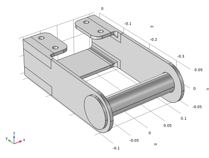
Browse to the model’s Application Libraries folder and double-click the file bracket_pin.mphbin.
|
|
6
|
Click
|
|
1
|
|
2
|
|
3
|
|
4
|
Click
|
|
1
|
In the Model Builder window, expand the Component 1 (comp1) > Solid Mechanics (solid) node, then click Linear Elastic Material 1.
|
|
1
|
|
2
|
|
3
|
|
5
|
|
1
|
In the Model Builder window, expand the Component 1 (comp1) > Mesh 1 > Free Tetrahedral 1 node, then click Size 1.
|
|
2
|
|
3
|
|
5
|
Click
|
|
1
|
|
2
|
Go to the Add Study window.
|
|
3
|
|
4
|
Click the Add Study button in the window toolbar.
|
|
5
|
|
1
|
|
2
|
|
1
|
|
2
|
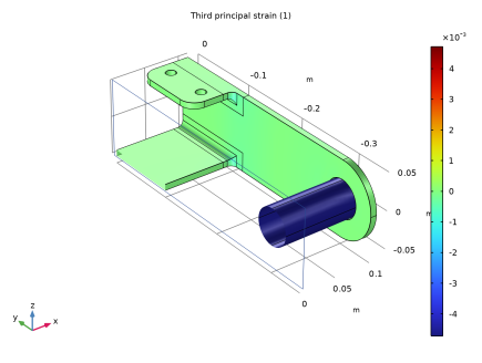
In the Settings window for Surface, click Replace Expression in the upper-right corner of the Expression section. From the menu, choose Component 1 (comp1) > Solid Mechanics > Strain > Principal strains > solid.ep3 - Third principal strain - 1.
|
|
3
|
|
4
|
|
5
|
|
6
|
|
7
|
|
8
|
|
9
|