|
|
|

|
1
|
|
2
|
In the Select Physics tree, select Structural Mechanics > Solid Mechanics (solid) and Structural Mechanics > Beam (beam).
|
|
3
|
Click Add.
|
|
4
|
Click
|
|
5
|
|
6
|
Click
|
|
1
|
|
2
|
|
3
|
Click
|
|
4
|
Browse to the model’s Application Libraries folder and double-click the file bolt_pretension_tutorial_parameters.txt.
|
|
1
|
|
2
|
|
3
|
|
1
|
|
2
|
|
3
|
|
1
|
|
2
|
|
3
|
|
4
|
|
5
|
|
6
|
Click
|
|
1
|
|
2
|
|
3
|
|
4
|
|
5
|
Click
|
|
1
|
|
2
|
|
3
|
|
4
|
|
5
|
|
6
|
|
7
|
|
8
|
|
9
|
|
1
|
|
2
|
|
3
|
|
4
|
|
5
|
|
6
|
|
7
|
|
8
|
Click
|
|
1
|
|
2
|
Select the object cyl1 only.
|
|
3
|
|
4
|
Select the Keep input objects checkbox.
|
|
5
|
|
6
|
Click
|
|
1
|
|
2
|
Select the object mov1 only.
|
|
3
|
|
4
|
Select the Keep input objects checkbox.
|
|
5
|
|
6
|
Click
|
|
1
|
|
2
|
In the Part Libraries window, select Structural Mechanics Module > Bolts > hex_bolt_no_thread in the tree.
|
|
3
|
Click
|
|
1
|
In the Model Builder window, under Component 1 (comp1) > Geometry 1 click Hex Bolt, No Thread 1 (pi1).
|
|
2
|
|
4
|
Locate the Position and Orientation of Output section. Find the Displacement subsection. In the xwi text field, type boltSpacing/2.
|
|
5
|
|
6
|
|
7
|
Click
|
|
8
|
Click to expand the Boundary Selections section. In the table, enter the following settings:
|
|
9
|
Click to expand the Domain Selections section. In the table, enter the following settings:
|
|
11
|
Click New Cumulative Selection.
|
|
12
|
|
13
|
Click OK.
|
|
1
|
|
2
|
|
3
|
|
4
|
Click
|
|
1
|
|
2
|
|
4
|
Locate the Position and Orientation of Output section. Find the Displacement subsection. In the xwi text field, type boltSpacing/2.
|
|
5
|
|
6
|
|
7
|
Click
|
|
8
|
Locate the Domain Selections section. In the table, enter the following settings:
|
|
1
|
|
2
|
|
3
|
In the Part Libraries window, select Structural Mechanics Module > Bolts > simple_bolt_drill in the tree.
|
|
4
|
Click
|
|
1
|
In the Model Builder window, under Component 1 (comp1) > Geometry 1 click Simple Bolt, With Drill 1 (pi3).
|
|
2
|
|
4
|
Locate the Position and Orientation of Output section. Find the Displacement subsection. In the xwi text field, type boltSpacing/2.
|
|
5
|
|
6
|
|
7
|
Locate the Boundary Selections section. In the table, enter the following settings:
|
|
8
|
Locate the Domain Selections section. In the table, enter the following settings:
|
|
9
|
Click
|
|
1
|
|
2
|
|
3
|
Select the object pi3(2) only.
|
|
4
|
|
5
|
Click
|
|
1
|
|
2
|
In the Settings window for Difference, type Difference: Bolt Holes and Cavity, Upper in the Label text field.
|
|
3
|
Select the object blk2 only.
|
|
4
|
|
5
|
|
6
|
|
7
|
Click
|
|
1
|
|
2
|
In the Settings window for Difference, type Difference: Bolt Holes and Cavity, Lower in the Label text field.
|
|
3
|
Locate the Difference section. Click to select the
|
|
4
|
Select the object blk1 only.
|
|
5
|
Clear the Keep objects to subtract checkbox.
|
|
6
|
Click
|
|
7
|
|
1
|
|
2
|
|
3
|
|
4
|
On the object dif1, select Point 2 only.
|
|
1
|
|
2
|
|
3
|
|
4
|
|
5
|
|
6
|
|
7
|
Click
|
|
1
|
|
2
|
|
3
|
Select the object c1 only.
|
|
4
|
|
5
|
Click
|
|
1
|
|
2
|
|
3
|
|
4
|
Click
|
|
1
|
|
2
|
|
3
|
Locate the Coordinates section. In the table, enter the following settings:
|
|
4
|
Locate the Selections of Resulting Entities section. Find the Cumulative selection subsection. Click New.
|
|
5
|
|
6
|
Click OK.
|
|
1
|
|
2
|
|
3
|
Select the object pol1 only.
|
|
4
|
|
5
|
Locate the Selections of Resulting Entities section. Find the Cumulative selection subsection. From the Contribute to list, choose Bolts and Nuts.
|
|
6
|
Click
|
|
1
|
|
2
|
|
3
|
Locate the Coordinates section. In the table, enter the following settings:
|
|
4
|
Locate the Selections of Resulting Entities section. Find the Cumulative selection subsection. From the Contribute to list, choose Beams.
|
|
5
|
Click
|
|
6
|
|
1
|
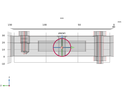
In the Model Builder window, expand the Component 1 (comp1) > Definitions > View 1 node, then click Clip Plane 1.
|
|
2
|
|
3
|
|
4
|
|
5
|
|
6
|
|
7
|
|
8
|
|
1
|
|
2
|
|
3
|
|
1
|
|
2
|
|
3
|
|
4
|
|
1
|
|
2
|
|
3
|
|
4
|
Specify the V vector as
|
|
1
|
|
2
|
Go to the Add Material window.
|
|
3
|
|
4
|
Right-click and choose Add to Global Materials.
|
|
5
|
|
1
|
|
2
|
|
3
|
|
4
|
|
1
|
|
2
|
|
1
|
|
2
|
|
1
|
|
2
|
|
3
|
|
1
|
|
2
|
|
3
|
|
4
|
|
5
|
Click OK.
|
|
6
|
|
8
|
|
1
|
|
2
|
|
4
|
|
1
|
|
2
|
|
3
|
|
5
|
|
1
|
|
2
|
|
3
|
Locate the Connection Settings section. From the Connection type list, choose Solid edges to beam points.
|
|
4
|
|
6
|
|
1
|
|
2
|
|
3
|
|
5
|
|
7
|
|
8
|
|
1
|
|
2
|
|
3
|
|
5
|
|
7
|
Locate the Connection Settings section. From the Connected region list, choose Connection criterion.
|
|
8
|
In the text field, type Z>thicLow-boltDia/2.
|
|
1
|
|
2
|
|
3
|
|
4
|
|
5
|
|
1
|
|
2
|
|
3
|
Locate the Definition section. In the Expression text field, type time==1 || abs(time-active)<0.001 || abs(time-(active+numBolt))<0.001.
|
|
1
|
|
2
|
|
3
|
Select the Compute tightening torque checkbox.
|
|
4
|
|
5
|
|
1
|
|
2
|
|
3
|
|
4
|
|
5
|
|
6
|
Select the Sequential tightening checkbox.
|
|
7
|
|
1
|
|
2
|
|
3
|
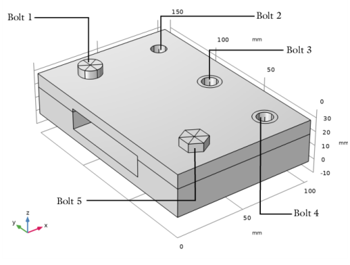
In the text field, type Bolt_5.
|
|
4
|
Locate the Boundary Selection section. From the Selection list, choose Pretension cut (Hex Bolt, No Thread 1).
|
|
5
|
|
6
|
|
7
|
Select the Sequential tightening checkbox.
|
|
8
|
|
1
|
|
2
|
|
3
|
In the text field, type Bolt_2.
|
|
5
|
|
6
|
|
7
|
Select the Sequential tightening checkbox.
|
|
8
|
|
1
|
Right-click Component 1 (comp1) > Beam (beam) > Bolt Pretension 1 > Bolt Selection 1 and choose Duplicate.
|
|
2
|
|
3
|
In the text field, type Bolt_3.
|
|
4
|
|
6
|
|
7
|
|
1
|
|
2
|
|
3
|
In the text field, type Bolt_4.
|
|
4
|
|
6
|
|
7
|
|
1
|
In the Model Builder window, under Component 1 (comp1) > Definitions click Identity Boundary Pair 1 (ap1).
|
|
2
|
|
3
|
Select the Manual control of selections and pair type checkbox.
|
|
4
|
|
5
|
|
6
|
|
1
|
|
2
|
|
3
|
Select the Manual control of selections and pair type checkbox.
|
|
4
|
|
5
|
|
1
|
|
2
|
|
3
|
|
1
|
|
1
|
|
3
|
|
4
|
|
1
|
|
1
|
|
2
|
|
3
|
|
1
|
In the Model Builder window, under Component 1 (comp1) > Beam (beam) click Linear Elastic Material 1.
|
|
2
|
|
3
|
Select the Geometrically linear formulation checkbox.
|
|
1
|
|
2
|
Go to the Add Material window.
|
|
3
|
|
4
|
Right-click and choose Add to Global Materials.
|
|
5
|
|
1
|
In the Model Builder window, under Component 1 (comp1) right-click Materials and choose More Materials > Material Link.
|
|
2
|
|
3
|
|
4
|
Locate the Geometric Entity Selection section. From the Geometric entity level list, choose Boundary.
|
|
1
|
|
2
|
|
4
|
|
1
|
|
2
|
|
3
|
From the list, choose User-controlled mesh.
|
|
1
|
|
2
|
|
3
|
|
1
|
|
2
|
|
3
|
|
5
|
|
6
|
Click the Custom button.
|
|
7
|
Locate the Element Size Parameters section.
|
|
8
|
|
9
|
Click
|
|
1
|
|
2
|
|
1
|
|
2
|
|
3
|
|
1
|
|
2
|
|
3
|
Click
|
|
5
|
|
6
|
Click
|
|
1
|
|
2
|
|
3
|
|
1
|
|
2
|
|
3
|
Select the Auxiliary sweep checkbox.
|
|
4
|
Click
|
|
6
|
|
7
|
|
8
|
Clear the Generate default plots checkbox.
|
|
1
|
|
2
|
|
3
|
Select the Plot checkbox.
|
|
1
|
In the Model Builder window, expand the Study 1 > Solver Configurations > Solution 1 (sol1) > Dependent Variables 1 node, then click Displacement Field (Material and Geometry Frames) (comp1.beam.uLin).
|
|
2
|
|
3
|
|
4
|
|
5
|
In the Model Builder window, under Study 1 > Solver Configurations > Solution 1 (sol1) > Dependent Variables 1 click Rotation Field (Material and Geometry Frames) (comp1.beam.thLin).
|
|
6
|
|
7
|
|
8
|
|
9
|
In the Model Builder window, expand the Study 1 > Solver Configurations > Solution 1 (sol1) > Stationary Solver 1 node, then click Fully Coupled 1.
|
|
10
|
|
11
|
|
12
|
In the Model Builder window, under Study 1 > Solver Configurations > Solution 1 (sol1) > Stationary Solver 1 click Parametric 1.
|
|
13
|
|
14
|
Select the Tuning of step size checkbox.
|
|
15
|
|
16
|
|
17
|
|
18
|
In the Model Builder window, under Study 1 > Solver Configurations > Solution 1 (sol1) > Stationary Solver 1 click Advanced.
|
|
19
|
|
20
|
Clear the Reuse sparsity pattern checkbox.
|
|
21
|
In the Model Builder window, under Study 1 > Solver Configurations > Solution 1 (sol1) > Stationary Solver 1 click Fully Coupled 1.
|
|
22
|
|
23
|
Select the Plot checkbox.
|
|
24
|
|
1
|
|
2
|
|
3
|
Click
|
|
4
|
|
5
|
|
6
|
Click OK.
|
|
7
|
|
9
|
Select the Apply conversions to expressions with the same dimensions checkbox.
|
|
10
|
Click
|
|
1
|
|
2
|
Go to the Result Templates window.
|
|
3
|
|
4
|
Click the Add Result Template button in the window toolbar.
|
|
5
|
|
1
|
|
2
|
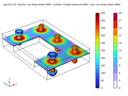
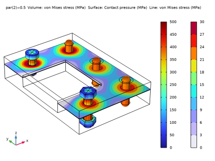
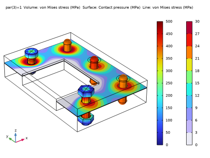
In the Settings window for 3D Plot Group, type Bolt Stress and Contact Pressure in the Label text field.
|
|
1
|
In the Model Builder window, expand the Results > Bolt Stress and Contact Pressure > Volume 1 node, then click Volume 1.
|
|
2
|
|
3
|
Select the Manual color range checkbox.
|
|
4
|
|
5
|
|
1
|
|
2
|
|
3
|
|
1
|
|
2
|
In the Settings window for Surface, click Replace Expression in the upper-right corner of the Expression section. From the menu, choose Component 1 (comp1) > Solid Mechanics > Contact > solid.Tn - Contact pressure - N/m².
|
|
3
|
|
4
|
|
5
|
|
6
|
|
1
|
|
2
|
|
3
|
Select the Scale factor checkbox.
|
|
1
|
|
2
|
|
3
|
|
4
|
|
5
|
|
6
|
Select the Radius scale factor checkbox.
|
|
7
|
|
8
|
|
1
|
|
2
|
In the Settings window for Deformation, click Replace Expression in the upper-right corner of the Expression section. From the menu, choose Component 1 (comp1) > Beam > Displacement > u2,v2,w2 - Displacement field.
|
|
1
|
|
2
|
|
1
|
|
2
|
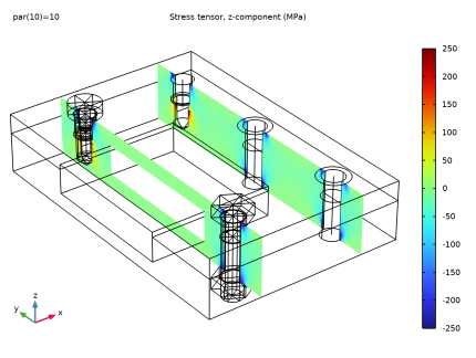
In the Settings window for 3D Plot Group, type Transverse Stress in the Bolt Planes in the Label text field.
|
|
1
|
|
2
|
|
3
|
|
4
|
|
5
|
|
6
|
|
7
|
|
8
|
|
1
|
|
3
|
|
1
|
|
2
|
|
1
|
|
2
|
In the Settings window for Global Evaluation, click Add Expression in the upper-right corner of the Expressions section. From the menu, choose Component 1 (comp1) > Solid Mechanics > Bolts > Bolt_1 > solid.pblt1.sblt1.F_bolt - Bolt force - N.
|
|
3
|
Locate the Expressions section. In the table, enter the following settings:
|
|
4
|
Click Add Expression in the upper-right corner of the Expressions section. From the menu, choose Component 1 (comp1) > Beam > Bolts > Bolt_2 > beam.pblt1.sblt1.F_bolt - Bolt force - N.
|
|
5
|
Locate the Expressions section. In the table, enter the following settings:
|
|
6
|
Click Add Expression in the upper-right corner of the Expressions section. From the menu, choose Component 1 (comp1) > Beam > Bolts > Bolt_3 > beam.pblt1.sblt2.F_bolt - Bolt force - N.
|
|
7
|
Locate the Expressions section. In the table, enter the following settings:
|
|
8
|
Click Add Expression in the upper-right corner of the Expressions section. From the menu, choose Component 1 (comp1) > Beam > Bolts > Bolt_4 > beam.pblt1.sblt3.F_bolt - Bolt force - N.
|
|
9
|
Locate the Expressions section. In the table, enter the following settings:
|
|
10
|
Click Add Expression in the upper-right corner of the Expressions section. From the menu, choose Component 1 (comp1) > Solid Mechanics > Bolts > Bolt_5 > solid.pblt1.sblt2.F_bolt - Bolt force - N.
|
|
11
|
Locate the Expressions section. In the table, enter the following settings:
|
|
12
|
|
1
|
|
2
|
|
3
|
|
1
|
|
2
|
In the Settings window for Global Evaluation, click Add Expression in the upper-right corner of the Expressions section. From the menu, choose Component 1 (comp1) > Solid Mechanics > Bolts > Bolt_1 > solid.pblt1.sblt1.M_pre - Tightening torque - N·m.
|
|
3
|
Click Add Expression in the upper-right corner of the Expressions section. From the menu, choose Component 1 (comp1) > Solid Mechanics > Bolts > Bolt_5 > solid.pblt1.sblt2.M_pre - Tightening torque - N·m.
|
|
1
|
|
2
|
|
1
|
|
2
|
|
3
|
|
4
|
|
1
|
|
2
|
|
3
|
|
4
|
|
1
|
|
2
|
|
3
|
Select the Modify model configuration for study step checkbox.
|
|
4
|
In the tree, select Component 1 (comp1) > Solid Mechanics (solid), Controls spatial frame > Boundary Load 1.
|
|
5
|
Right-click and choose Disable.
|
|
1
|
|
2
|
Go to the Add Study window.
|
|
3
|
|
4
|
Right-click and choose Add Study.
|
|
5
|
|
1
|
|
2
|
Select the Auxiliary sweep checkbox.
|
|
3
|
Click
|
|
5
|
Click to expand the Values of Dependent Variables section. Find the Initial values of variables solved for subsection. From the Settings list, choose User controlled.
|
|
6
|
|
7
|
|
8
|
Find the Values of variables not solved for subsection. From the Settings list, choose User controlled.
|
|
9
|
|
10
|
|
1
|
|
2
|
|
3
|
In the Model Builder window, expand the Study 2 > Solver Configurations > Solution 2 (sol2) > Dependent Variables 1 node, then click Rotation Field (Material and Geometry Frames) (comp1.beam.thLin).
|
|
4
|
|
5
|
|
6
|
|
7
|
In the Model Builder window, under Study 2 > Solver Configurations > Solution 2 (sol2) > Dependent Variables 1 click Displacement Field (Material and Geometry Frames) (comp1.beam.uLin).
|
|
8
|
|
9
|
|
10
|
|
11
|
In the Model Builder window, expand the Study 2 > Solver Configurations > Solution 2 (sol2) > Stationary Solver 1 node, then click Advanced.
|
|
12
|
|
13
|
Clear the Reuse sparsity pattern checkbox.
|
|
14
|
In the Model Builder window, under Study 2 > Solver Configurations > Solution 2 (sol2) > Stationary Solver 1 click Fully Coupled 1.
|
|
15
|
|
16
|
|
17
|
|
18
|
|
19
|
Clear the Generate default plots checkbox.
|
|
20
|
|
1
|
|
2
|
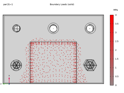
In the Settings window for 3D Plot Group, type Bolt Stress and Contact Pressure, Service Load in the Label text field.
|
|
3
|
|
4
|
|
5
|
|
6
|
|
7
|
|
8
|
|
9
|
|
1
|
|
2
|
Go to the Result Templates window.
|
|
3
|
In the tree, select Study 2/Solution 2 (sol2) > Solid Mechanics > Applied Loads (solid) > Boundary Loads (solid).
|
|
4
|
Click the Add Result Template button in the window toolbar.
|
|
5
|
|
1
|
|
2
|
|
1
|
|
2
|
In the Settings window for Evaluation Group, type Bolt Shear Force (service load) in the Label text field.
|
|
3
|
|
1
|
|
2
|
In the Settings window for Global Evaluation, click Add Expression in the upper-right corner of the Expressions section. From the menu, choose Component 1 (comp1) > Solid Mechanics > Bolts > Bolt_1 > solid.pblt1.sblt1.F_shear - Bolt shear force - N.
|
|
3
|
Locate the Expressions section. In the table, enter the following settings:
|
|
4
|
Click Add Expression in the upper-right corner of the Expressions section. From the menu, choose Component 1 (comp1) > Beam > Bolts > Bolt_2 > beam.pblt1.sblt1.F_shear - Bolt shear force - N.
|
|
5
|
Locate the Expressions section. In the table, enter the following settings:
|
|
6
|
Click Add Expression in the upper-right corner of the Expressions section. From the menu, choose Component 1 (comp1) > Beam > Bolts > Bolt_3 > beam.pblt1.sblt2.F_shear - Bolt shear force - N.
|
|
7
|
Locate the Expressions section. In the table, enter the following settings:
|
|
8
|
Click Add Expression in the upper-right corner of the Expressions section. From the menu, choose Component 1 (comp1) > Beam > Bolts > Bolt_4 > beam.pblt1.sblt3.F_shear - Bolt shear force - N.
|
|
9
|
Locate the Expressions section. In the table, enter the following settings:
|
|
10
|
Click Add Expression in the upper-right corner of the Expressions section. From the menu, choose Component 1 (comp1) > Solid Mechanics > Bolts > Bolt_5 > solid.pblt1.sblt2.F_shear - Bolt shear force - N.
|
|
11
|
Locate the Expressions section. In the table, enter the following settings:
|
|
12
|