|
|
|
|
•
|
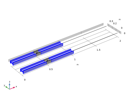
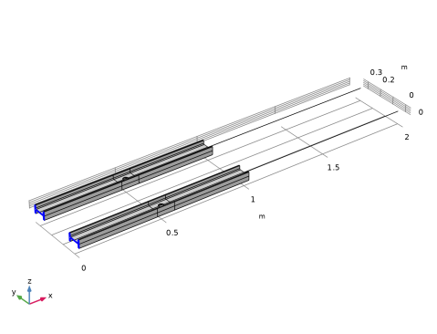
Length of each beam: 2 m. The transition is at the midpoint.
|
|
•
|
Cross section of the beam: European standard I-section beam (IPE 80) of 80-by-46 mm with 3.8 mm web thickness and 5.2 mm flange thickness.
|
|
•
|
Radius of the circular hole: 15 mm.
|
|
•
|
|
•
|
|
1
|
|
2
|
|
3
|
Click Add.
|
|
4
|
|
5
|
Click Add.
|
|
6
|
Click
|
|
7
|
|
8
|
Click
|
|
1
|
|
2
|
|
3
|
Click
|
|
4
|
Browse to the model’s Application Libraries folder and double-click the file beam_solid_connection_parameters.txt.
|
|
1
|
In the Model Builder window, right-click Global Definitions and choose Load and Constraint Groups > Load Group.
|
|
2
|
|
3
|
|
1
|
|
2
|
|
3
|
|
1
|
|
2
|
|
3
|
|
1
|
|
2
|
|
3
|
|
1
|
|
2
|
|
3
|
|
1
|
|
2
|
|
3
|
|
1
|
|
2
|
|
3
|
|
4
|
|
5
|
|
6
|
|
7
|
Click
|
|
8
|
|
1
|
|
2
|
|
3
|
|
4
|
Click
|
|
1
|
|
2
|
In the Part Libraries window, select Structural Mechanics Module > Beams > European Standard > IPE_beam in the tree.
|
|
3
|
Click
|
|
1
|
In the Model Builder window, under Component 1 (comp1) > Geometry 1 > Work Plane 1 (wp1) > Plane Geometry click European IPE-beam 1 (pi1).
|
|
2
|
|
1
|
|
2
|
|
4
|
Select the Reverse direction checkbox.
|
|
5
|
Click
|
|
1
|
|
2
|
|
3
|
|
4
|
|
5
|
|
6
|
|
7
|
Click
|
|
1
|
|
2
|
Select the object ext1 only.
|
|
3
|
|
4
|
|
5
|
Select the object cyl1 only.
|
|
6
|
Click
|
|
1
|
|
2
|
Click in the Graphics window and then press Ctrl+A to select both objects.
|
|
3
|
|
4
|
|
5
|
Click
|
|
6
|
|
1
|
|
2
|
|
3
|
|
4
|
|
5
|
Click
|
|
1
|
|
2
|
|
3
|
|
4
|
Click
|
|
1
|
|
2
|
|
3
|
|
4
|
|
5
|
|
6
|
Click
|
|
1
|
|
2
|
|
3
|
|
4
|
|
5
|
Click
|
|
1
|
|
2
|
Select the object par2(2) only.
|
|
3
|
|
1
|
|
2
|
Select the object par2(1) only.
|
|
3
|
|
1
|
|
2
|
|
3
|
|
4
|
|
1
|
|
2
|
|
3
|
|
4
|
On the object fin, select Boundaries 1 and 69 only.
|
|
1
|
|
2
|
|
3
|
|
4
|
On the object fin, select Boundaries 68 and 136 only.
|
|
1
|
|
2
|
|
3
|
|
4
|
On the object fin, select Points 178 and 180 only.
|
|
1
|
|
3
|
|
4
|
|
5
|
|
6
|
|
7
|
|
1
|
|
2
|
Go to the Add Material window.
|
|
3
|
|
4
|
Click the right end of the Add to Component split button in the window toolbar.
|
|
5
|
From the menu, choose Add to Global Materials.
|
|
6
|
|
1
|
|
2
|
|
3
|
|
1
|
|
2
|
|
3
|
|
1
|
|
2
|
|
3
|
|
1
|
|
2
|
|
3
|
Click
|
|
1
|
|
2
|
|
3
|
|
4
|
|
5
|
|
6
|
|
7
|
|
8
|
|
9
|
|
10
|
|
11
|
|
12
|
|
13
|
|
14
|
|
15
|
|
16
|
|
17
|
|
18
|
|
1
|
|
2
|
|
3
|
|
4
|
Specify the V vector as
|
|
1
|
|
2
|
|
3
|
|
4
|
|
5
|
|
1
|
|
2
|
|
3
|
|
4
|
|
5
|
|
1
|
|
2
|
|
3
|
|
4
|
|
5
|
|
6
|
|
1
|
|
2
|
|
3
|
|
4
|
|
5
|
|
1
|
|
2
|
|
3
|
|
4
|
|
5
|
|
1
|
|
2
|
|
3
|
|
4
|
|
5
|
|
1
|
|
2
|
In the Settings window for Solid–Beam Connection, type Solid-Beam Connection Transition in the Label text field.
|
|
3
|
Locate the Connection Settings section. From the Connection type list, choose Solid boundaries to beam points, transition.
|
|
4
|
Select the Manual control of selections checkbox.
|
|
5
|
|
7
|
|
1
|
|
2
|
In the Settings window for Solid–Beam Connection, type Solid-Beam Connection General in the Label text field.
|
|
3
|
|
5
|
|
1
|
|
1
|
|
2
|
|
3
|
Click the Custom button.
|
|
4
|
Locate the Element Size Parameters section.
|
|
5
|
|
6
|
Click
|
|
1
|
|
2
|
|
3
|
|
1
|
|
2
|
|
3
|
|
4
|
Click
|
|
6
|
|
7
|
|
8
|
Click
|
|
1
|
|
2
|
|
3
|
|
4
|
Click
|
|
6
|
|
7
|
In the Relative placement of vertices along edge text field, type range(0,0.015,0.92) range(0.92,0.005,1).
|
|
8
|
Select the Reverse direction checkbox.
|
|
9
|
Click
|
|
1
|
|
2
|
|
3
|
|
1
|
|
2
|
|
3
|
Click the Custom button.
|
|
4
|
Locate the Element Size Parameters section.
|
|
5
|
|
6
|
Click
|
|
1
|
|
1
|
|
2
|
|
3
|
|
4
|
Click
|
|
1
|
|
2
|
|
3
|
In the Solve for column of the table, under Component 1 (comp1), clear the checkboxes for Solid Mechanics (solid) and Beam (beam).
|
|
4
|
In the Solve for column of the table, under Component 1 (comp1) > Multiphysics, clear the checkbox for Solid-Beam Connection General (sbc2).
|
|
5
|
Click to expand the Values of Dependent Variables section. Find the Initial values of variables solved for subsection. From the Settings list, choose User controlled.
|
|
1
|
|
2
|
|
3
|
Select the Define load cases checkbox.
|
|
4
|
Click
|
|
1
|
|
2
|
|
3
|
|
4
|
|
5
|
In the Model Builder window, expand the Study 1 > Solver Configurations > Solution 1 (sol1) > Dependent Variables 1 node, then click Study 1 > Solver Configurations > Solution 1 (sol1) > Dependent Variables 2.
|
|
6
|
|
7
|
|
8
|
In the Model Builder window, expand the Study 1 > Solver Configurations > Solution 1 (sol1) > Dependent Variables 2 node, then click Displacement Field (comp1.u).
|
|
9
|
|
10
|
|
11
|
|
12
|
In the Model Builder window, under Study 1 > Solver Configurations > Solution 1 (sol1) > Dependent Variables 2 click Displacement Field (comp1.u2).
|
|
13
|
|
14
|
|
15
|
|
16
|
In the Model Builder window, under Study 1 > Solver Configurations > Solution 1 (sol1) > Dependent Variables 2 click Warping Function (comp1.sbc1.ww).
|
|
17
|
|
18
|
Clear the Solve for this field checkbox.
|
|
19
|
In the Model Builder window, under Study 1 > Solver Configurations > Solution 1 (sol1) > Dependent Variables 2 click Warping Constant (comp1.sbc1.C0).
|
|
20
|
|
21
|
Clear the Solve for this state checkbox.
|
|
22
|
In the Model Builder window, under Study 1 > Solver Configurations > Solution 1 (sol1) > Dependent Variables 2 click Warping Constant (comp1.sbc1.C1).
|
|
23
|
|
24
|
Clear the Solve for this state checkbox.
|
|
25
|
In the Model Builder window, under Study 1 > Solver Configurations > Solution 1 (sol1) > Dependent Variables 2 click Warping Constant (comp1.sbc1.C2).
|
|
26
|
|
27
|
Clear the Solve for this state checkbox.
|
|
28
|
|
1
|
|
2
|
|
3
|
Clear the Show grid checkbox.
|
|
1
|
|
2
|
|
3
|
|
4
|
|
1
|
|
2
|
|
3
|
|
4
|
|
1
|
|
2
|
|
3
|
|
4
|
|
5
|
|
6
|
|
1
|
|
2
|
|
3
|
|
1
|
|
2
|
|
3
|
|
4
|
|
1
|
|
2
|
|
3
|
|
4
|
|
5
|
|
1
|
|
2
|
|
3
|
|
4
|
|
1
|
|
3
|
|
4
|
|
1
|
|
2
|
|
3
|
|
4
|
|
1
|
|
2
|
|
3
|
|
4
|
|
5
|
|
1
|
|
2
|
|
3
|
|
1
|
|
2
|
In the Settings window for Arrow Surface, click Replace Expression in the upper-right corner of the Expression section. From the menu, choose Component 1 (comp1) > Solid Mechanics > Stress > solid.Tax,...,solid.Taz - Traction (force/area) (spatial frame).
|
|
3
|
|
4
|
|
1
|
|
2
|
|
3
|
|
4
|
|
5
|
|
6
|
|
1
|
|
2
|
|
3
|
|
4
|