|
|
|


|
1
|
|
2
|
|
3
|
Click Add.
|
|
4
|
|
5
|
Click Add.
|
|
6
|
Click
|
|
7
|
|
8
|
Click
|
|
1
|
|
2
|
|
1
|
|
2
|
|
3
|
Click
|
|
4
|
Browse to the model’s Application Libraries folder and double-click the file aluminum_extrusion_fsi.mphbin.
|
|
5
|
Click
|
|
6
|
|
7
|
|
1
|
|
2
|
In the Geometry Cleanup dialog that opens, click Clean up Automatically to automatically clean up the geometry.
|
|
1
|
|
2
|
|
1
|
|
2
|
|
3
|
|
1
|
|
2
|
|
3
|
|
1
|
In the Model Builder window, under Component 1 (comp1) > Heat Transfer in Solids and Fluids (ht) click Fluid 1.
|
|
3
|
|
4
|
Click
|
|
5
|
|
6
|
Click OK.
|
|
1
|
|
2
|
|
3
|
|
4
|
|
1
|
|
2
|
|
3
|
Click
|
|
1
|
|
2
|
Go to the Add Material window.
|
|
3
|
|
4
|
Click the Add to Component button in the window toolbar.
|
|
5
|
|
2
|
|
1
|
|
2
|
|
3
|
|
4
|
Locate the Material Contents section. In the table, enter the following settings:
|
|
1
|
In the Model Builder window, under Component 1 (comp1) > Materials right-click Structural steel (mat1) and choose Duplicate.
|
|
2
|
|
3
|
|
4
|
|
1
|
|
3
|
|
4
|
Click
|
|
5
|
|
6
|
|
7
|
Click OK.
|
|
8
|
|
9
|
In the text field, type T_container.
|
|
1
|
|
3
|
|
4
|
Click
|
|
5
|
|
6
|
Click OK.
|
|
7
|
|
8
|
In the text field, type T_pd1.
|
|
1
|
|
2
|
In the Show More Options dialog, in the tree, select the checkbox for the node Physics > Advanced Physics Options.
|
|
3
|
Click OK.
|
|
4
|
|
5
|
|
6
|
Find the Pseudo time stepping subsection. From the Use pseudo time stepping for stationary equation form list, choose Off.
|
|
1
|
|
2
|
|
3
|
|
1
|
|
1
|
|
3
|
|
4
|
Click the Velocity field button.
|
|
5
|
|
1
|
|
2
|
|
3
|
|
4
|
|
1
|
|
3
|
|
4
|
|
1
|
In the Model Builder window, under Component 1 (comp1) > Heat Transfer in Solids and Fluids (ht) click Initial Values 1.
|
|
2
|
|
3
|
|
1
|
|
3
|
|
4
|
|
1
|
|
3
|
|
4
|
|
5
|
|
6
|
|
1
|
|
2
|
|
3
|
|
4
|
|
5
|
|
6
|
|
1
|
|
1
|
|
2
|
|
3
|
|
4
|
|
5
|
|
1
|
|
2
|
|
1
|
|
2
|
|
3
|
|
1
|
In the Model Builder window, under Component 1 (comp1) > Solid Mechanics (solid) click Linear Elastic Material 1.
|
|
2
|
|
3
|
|
1
|
|
1
|
|
1
|
In the Physics toolbar, click
|
|
2
|
|
3
|
|
1
|
|
1
|
|
1
|
|
2
|
|
3
|
Click the Custom button.
|
|
4
|
Locate the Element Size Parameters section.
|
|
5
|
|
6
|
|
7
|
Click
|
|
1
|
|
2
|
|
3
|
|
1
|
|
2
|
|
3
|
|
4
|
Click
|
|
1
|
|
2
|
|
3
|
Click the Custom button.
|
|
4
|
Locate the Element Size Parameters section.
|
|
5
|
|
1
|
|
2
|
|
3
|
|
5
|
|
6
|
Locate the Element Size Parameters section.
|
|
7
|
|
1
|
|
2
|
|
3
|
|
5
|
|
6
|
Locate the Element Size Parameters section.
|
|
7
|
|
1
|
|
2
|
|
3
|
|
4
|
Click
|
|
1
|
|
2
|
|
3
|
In the Solve for column of the table, under Component 1 (comp1), clear the checkbox for Solid Mechanics (solid).
|
|
4
|
In the Solve for column of the table, under Component 1 (comp1) > Multiphysics, clear the checkboxes for Fluid–Structure Interaction 1 (fsi1) and Thermal Expansion 1 (te1).
|
|
1
|
|
2
|
|
3
|
In the Solve for column of the table, under Component 1 (comp1), clear the checkboxes for Heat Transfer in Solids and Fluids (ht) and Laminar Flow (spf).
|
|
4
|
In the Solve for column of the table, under Component 1 (comp1) > Multiphysics, clear the checkbox for Nonisothermal Flow 1 (nitf1).
|
|
1
|
|
2
|
|
3
|
In the Model Builder window, expand the Study 1 > Solver Configurations > Solution 1 (sol1) > Stationary Solver 2 node.
|
|
4
|
Right-click Study 1 > Solver Configurations > Solution 1 (sol1) > Stationary Solver 2 and choose Iterative.
|
|
5
|
|
1
|
|
2
|
|
3
|
|
4
|
|
5
|
|
6
|
|
1
|
|
2
|
|
3
|
|
4
|
|
1
|
|
2
|
|
3
|
|
1
|
|
2
|
|
3
|
|
4
|
|
5
|
|
6
|
|
7
|
|
1
|
|
2
|
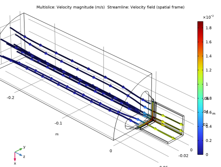
In the Settings window for Streamline, click Replace Expression in the upper-right corner of the Expression section. From the menu, choose Component 1 (comp1) > Laminar Flow > Velocity and pressure > u,v,w - Velocity field (spatial frame).
|
|
3
|
|
4
|
|
5
|
|
6
|
Locate the Coloring and Style section. Find the Line style subsection. From the Type list, choose Ribbon.
|
|
7
|
|
8
|
Select the Width scale factor checkbox.
|
|
9
|
|
10
|
|
11
|
Click to expand the Inherit Style section.
|
|
1
|
|
2
|
In the Settings window for Color Expression, click Replace Expression in the upper-right corner of the Expression section. From the menu, choose Component 1 (comp1) > Laminar Flow > Velocity and pressure > spf.U - Velocity magnitude - m/s.
|
|
1
|
|
2
|
|
3
|
|
4
|
|
1
|
|
2
|
|
3
|
|
4
|
|
5
|
Click
|
|
1
|
|
2
|
Use the Graphics toolbox to get a satisfying view.
|
|
3
|
|
4
|
Select the Lock camera checkbox.
|
|
1
|
|
2
|
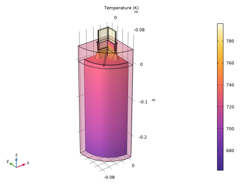
In the Settings window for 3D Plot Group, type Velocity and Outside Temperature in the Label text field.
|
|
3
|
|
4
|
|
1
|
|
2
|
|
3
|
Click Yes to confirm.
|
|
1
|
|
1
|
|
2
|
|
3
|
|
4
|
|
1
|
|
2
|
|
3
|
|
4
|
|
5
|
|
1
|
|
2
|
|
3
|
|
1
|
|
2
|
|
3
|
|
4
|
|
1
|
|
2
|
Browse to a suitable folder, enter the filename aluminum_extrusion_fsi_geom_sequence.mph, and then click Save.
|
|
1
|
|
2
|
|
3
|
Select the Design Module Boolean operations checkbox.
|
|
4
|
|
1
|
|
2
|
|
3
|
|
4
|
|
5
|
|
6
|
Click to expand the Layers section. In the table, enter the following settings:
|
|
7
|
Clear the Layers on side checkbox.
|
|
8
|
Select the Layers on top checkbox.
|
|
1
|
|
2
|
|
3
|
|
4
|
|
5
|
|
1
|
|
2
|
Click in the Graphics window and then press Ctrl+A to select both objects.
|
|
1
|
|
2
|
|
3
|
|
4
|
|
5
|
|
6
|
|
7
|
|
8
|
|
1
|
|
2
|
Click in the Graphics window and then press Ctrl+A to select both objects.
|
|
1
|
|
2
|
|
3
|
|
4
|
|
5
|
|
6
|
|
7
|
|
1
|
|
2
|
|
3
|
|
1
|
|
2
|
|
3
|
|
4
|
|
5
|
On the object cone1, select Point 5 only.
|
|
1
|
|
2
|
|
3
|
|
4
|
Select the object cone1 only.
|
|
1
|
In the Model Builder window, under Component 1 (comp1) > Geometry 1 right-click Work Plane 1 (wp1) and choose Extrude.
|
|
2
|
|
3
|
|
4
|
On the object cone2, select Point 5 only.
|
|
1
|
|
2
|
|
3
|
|
4
|
Select the Keep input objects checkbox.
|
|
5
|
|
6
|
|
7
|
|
1
|
|
2
|
|
3
|
|
4
|
Clear the Keep interior boundaries checkbox.
|
|
5
|
|
6
|
In the Tools window for Replace Faces, in the Graphics window toolbar, click
|
|
7
|
On the object uni2, select Boundaries 3, 4, 6–9, 12, 14–24, and 26–29 only.
|
|
8
|
|
9
|
Click Replace Selected.
|
|
1
|
|
2
|
|
3
|
|
4
|
On the object rfa1, select Edge 15 only.
|
|
5
|
Locate the Radii section. In the table, enter the following settings:
|
|
1
|
|
2
|
|
3
|
Select the Group by continuous tangent checkbox.
|
|
4
|
On the object fil1, select Edges 4, 5, 8, 10, 18–20, 23, 25, and 27 only.
|
|
5
|
|
1
|
|
2
|
|
3
|
|
1
|
|
2
|
|
3
|
|
4
|
|
5
|
|
6
|
|
1
|
Right-click Component 1 (comp1) > Geometry 1 > Work Plane 2 (wp2) > Plane Geometry > Rectangle 1 (r1) and choose Duplicate.
|
|
2
|
|
3
|
|
4
|
|
1
|
|
2
|
Select the object r1 only.
|
|
3
|
|
4
|
|
5
|
|
6
|
Select the object r2 only.
|
|
1
|
|
2
|
On the object dif1, select Points 1–3 and 5 only.
|
|
3
|
|
4
|
|
1
|
|
2
|
On the object fil1, select Point 10 only.
|
|
3
|
|
4
|
|
1
|
|
2
|
On the object fil2, select Point 6 only.
|
|
3
|
|
4
|
|
1
|
In the Model Builder window, under Component 1 (comp1) > Geometry 1 right-click Work Plane 2 (wp2) and choose Extrude.
|
|
2
|
|
1
|
|
2
|
|
3
|
|
4
|
On the object ext2, select Boundary 6 only.
|
|
1
|
|
2
|
|
3
|
|
4
|
Select the object ext2 only.
|
|
1
|
|
2
|
Select the object cro1 only.
|
|
3
|
|
4
|
|
5
|
|
6
|
|
1
|
In the Model Builder window, under Component 1 (comp1) > Geometry 1 right-click Work Plane 3 (wp3) and choose Duplicate.
|
|
2
|
|
3
|
|
4
|
In the tree, select ext2.
|
|
5
|
On the object int1, select Boundary 7 only.
|
|
6
|
|
1
|
In the Model Builder window, expand the Component 1 (comp1) > Geometry 1 > Work Plane 4 (wp4) > Plane Geometry node, then click Offset 1 (off1).
|
|
2
|
|
3
|
|
1
|
|
2
|
|
1
|
|
2
|
|
3
|
|
4
|
|
1
|
|
2
|
|
3
|
|
4
|
On the object ext2, select Domain 1 only.
|
|
1
|
|
2
|
|
3
|
|
4
|
Clear the Keep interior boundaries checkbox.
|
|
1
|
|
2
|
Select the object int1 only.
|
|
3
|
|
4
|
|
5
|
Select the object uni3 only.
|
|
1
|
|
2
|
|
3
|
Select the Group by continuous tangent checkbox.
|
|
4
|
On the object dif1, select Edges 25, 26, 29, 35, 38, 50, 56, 57, 64, 67, 76, and 79 only.
|
|
5
|
|
1
|
|
2
|
|
3
|
Select the Group by continuous tangent checkbox.
|
|
4
|
On the object fil3, select Edges 14, 16, 18, 36, 50, 51, 53, 75, 89, 91, and 108 only.
|
|
5
|
|
1
|
|
2
|
|
3
|
|
4
|
On the object ext2, select Domain 1 only.
|
|
5
|
On the object fil4, select Domain 3 only.
|
|
6
|
|
1
|
|
2
|
|
3
|
|
4
|
Clear the Keep interior boundaries checkbox.
|
|
1
|
|
2
|
|
3
|
|
4
|
|
5
|
|
6
|
|
7
|
|
8
|
|
9
|
|
10
|
|
11
|
|
1
|
|
2
|
Select the object cyl3 only.
|
|
3
|
|
4
|
|
5
|
|
6
|
|
7
|
|
8
|
|
9
|
|
10
|
|
11
|
|
12
|
|
1
|
|
2
|
Select the object extract2(4) only.
|
|
3
|
|
4
|
|
5
|
Select the object rot2 only.
|
|
1
|
|
2
|
Select the object dif2 only.
|
|
3
|
|
4
|
|
5
|
Select the object uni4 only.
|
|
6
|
Select the Keep objects to subtract checkbox.
|
|
1
|
|
2
|
Click in the Graphics window and then press Ctrl+A to select all objects.
|
|
1
|
|
2
|
|
1
|
|
2
|
On the object fin, select Boundary 92 only.
|
|
1
|
|
2
|
On the object clf1, select Edges 18 and 20 only.
|
|
3
|
|
4
|
|
5
|
|
6
|
|
7
|
Click
|