|
|
|
|
1
|
|
2
|
|
3
|
Click Add.
|
|
4
|
|
5
|
Click Add.
|
|
6
|
Click
|
|
7
|
In the Select Study tree, select Preset Studies for Selected Physics Interfaces > Semiconductor > Semiconductor Equilibrium.
|
|
8
|
Click
|
|
1
|
|
2
|
|
3
|
|
1
|
|
2
|
|
3
|
Click
|
|
4
|
Browse to the model’s Application Libraries folder and double-click the file pin_reverse_recovery_parameters.txt.
|
|
1
|
|
2
|
|
1
|
|
2
|
|
3
|
Select the Cutoff checkbox.
|
|
4
|
|
5
|
Select the Size of transition zone at cutoff checkbox.
|
|
1
|
|
2
|
Go to the Add Material window.
|
|
3
|
|
4
|
Click the Add to Component button in the window toolbar.
|
|
5
|
|
1
|
|
2
|
|
3
|
|
1
|
|
2
|
|
3
|
|
4
|
|
5
|
|
1
|
|
2
|
|
3
|
|
4
|
|
5
|
|
1
|
|
2
|
|
3
|
|
4
|
|
5
|
|
6
|
|
1
|
In the Model Builder window, expand the Geometric Doping Model 1 node, then click Boundary Selection for Doping Profile 1.
|
|
1
|
|
2
|
|
3
|
|
4
|
|
5
|
|
6
|
|
7
|
|
1
|
In the Model Builder window, expand the Geometric Doping Model 2 node, then click Boundary Selection for Doping Profile 1.
|
|
1
|
|
1
|
|
3
|
|
4
|
|
1
|
|
2
|
|
3
|
|
4
|
Locate the Shockley–Read–Hall Recombination section. From the τn list, choose User defined. In the associated text field, type 1[us].
|
|
5
|
|
1
|
|
2
|
|
4
|
|
1
|
|
2
|
|
4
|
|
1
|
|
2
|
|
1
|
|
2
|
|
4
|
|
1
|
|
2
|
|
4
|
Locate the Device Parameters section. In the vsrc text field, type Von+(Voff-Von)*rm1((t+10[ns])/10[ns]).
|
|
1
|
|
2
|
In the Settings window for Semiconductor Equilibrium, locate the Physics and Variables Selection section.
|
|
3
|
In the Solve for column of the table, under Component 1 (comp1), clear the checkbox for Electrical Circuit (cir).
|
|
1
|
|
2
|
|
3
|
Select the Modify model configuration for study step checkbox.
|
|
4
|
|
5
|
Click
|
|
6
|
|
7
|
Click
|
|
1
|
|
2
|
|
3
|
Select the Modify model configuration for study step checkbox.
|
|
4
|
|
5
|
Click
|
|
6
|
|
7
|
|
8
|
|
9
|
|
1
|
|
2
|
|
3
|
|
4
|
|
5
|
In the Model Builder window, under Study 1 > Solver Configurations > Solution 1 (sol1) click Dependent Variables 3.
|
|
6
|
|
7
|
|
8
|
|
1
|
|
2
|
|
3
|
|
4
|
|
1
|
|
2
|
|
3
|
|
4
|
|
5
|
|
6
|
|
7
|
|
8
|
|
9
|
|
10
|
|
1
|
|
2
|
|
1
|
|
2
|
|
3
|
|
1
|
|
2
|
|
1
|
|
2
|
|
4
|
|
1
|
|
2
|
|
1
|
|
2
|
|
4
|
|
1
|
|
2
|
|
1
|
|
2
|
|
3
|
Locate the Plot Settings section.
|
|
4
|
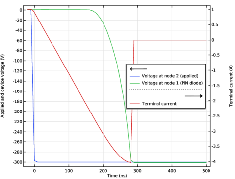
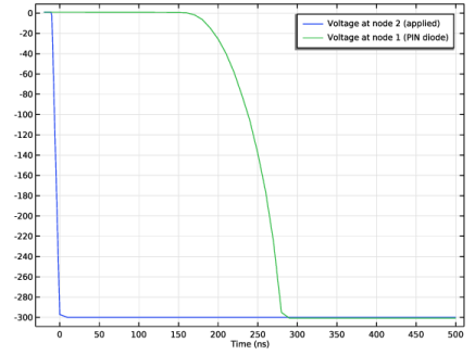
Select the y-axis label checkbox. In the associated text field, type Applied and device voltage (V).
|
|
5
|
Select the Two y-axes checkbox.
|
|
6
|
|
7
|
|
8
|