|
|
|
|
•
|
|
•
|
|
1
|
|
2
|
|
3
|
Click Add.
|
|
4
|
Click
|
|
5
|
|
6
|
Click
|
|
1
|
|
2
|
In the Settings window for Parameters, type Parameters 1: Lens Prescription in the Label text field. The lens prescription will be added when the geometry sequence is inserted in the following section.
|
|
1
|
|
2
|
|
3
|
|
4
|
Browse to the model’s Application Libraries folder and double-click the file petzval_lens_optimization_parameters.txt.
|
|
1
|
|
2
|
|
3
|
|
4
|
|
5
|
|
6
|
Browse to the model’s Application Libraries folder and double-click the file petzval_lens_optimization_geom_sequence.mph.
|
|
7
|
|
8
|
|
9
|
|
1
|
|
2
|
Go to the Add Material window.
|
|
3
|
|
4
|
Click the Add to Component button in the window toolbar.
|
|
5
|
|
6
|
Click the Add to Component button in the window toolbar.
|
|
7
|
|
8
|
Click the Add to Component button in the window toolbar.
|
|
9
|
|
10
|
Click the Add to Component button in the window toolbar.
|
|
11
|
|
1
|
|
2
|
|
1
|
|
2
|
|
3
|
|
1
|
|
2
|
|
3
|
|
1
|
|
2
|
|
3
|
|
1
|
|
2
|
|
3
|
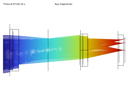
From the Wavelength distribution of released rays list, choose Polychromatic, specify vacuum wavelength. The list of polychromatic wavelengths will be entered below.
|
|
4
|
In the Maximum number of secondary rays text field, type 0. In this simulation stray light is not being traced, so reflected rays will not be produced at the lens surfaces.
|
|
5
|
Locate the Material Properties of Exterior and Unmeshed Domains section. From the Optical dispersion model list, choose Air, Edlen (1953). The lenses are assumed to be surrounded by air at room temperature.
|
|
1
|
In the Model Builder window, under Component 1 (comp1) > Geometrical Optics (gop) click Medium Properties 1.
|
|
2
|
|
3
|
From the Refractive index of domains list, choose Get dispersion model from material. Each of the materials added above contain the optical dispersion coefficients which can be used to compute the refractive index as a function of wavelength.
|
|
1
|
|
2
|
|
3
|
|
1
|
|
2
|
|
3
|
|
4
|
|
5
|
|
6
|
|
7
|
|
8
|
|
9
|
|
10
|
|
1
|
|
2
|
|
3
|
|
4
|
|
1
|
|
2
|
|
3
|
|
4
|
|
1
|
|
2
|
|
3
|
|
4
|
|
1
|
|
2
|
|
3
|
|
4
|
|
1
|
|
2
|
|
3
|
|
1
|
|
2
|
|
3
|
|
4
|
|
5
|
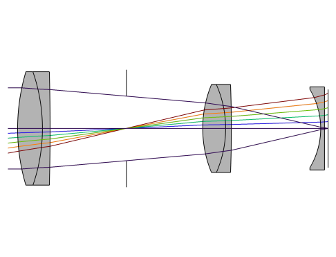
In the Lengths text field, type 0 200. The maximum optical path length is sufficient for rays released at large field angles to reach the image plane.
|
|
6
|
|
1
|
|
2
|
Clear the Show legends checkbox.
|
|
3
|
|
4
|
|
1
|
|
2
|
|
3
|
|
1
|
|
2
|
|
3
|
|
4
|
|
5
|
|
6
|
|
7
|
|
8
|
|
1
|
|
2
|
|
3
|
|
4
|
Browse to the model’s Application Libraries folder and double-click the file petzval_lens_optimization_opt_parameters.txt.
|
|
1
|
|
2
|
|
1
|
|
2
|
Go to the Add Study window.
|
|
3
|
Find the Studies subsection. In the Select Study tree, select Preset Studies for Selected Physics Interfaces > Ray Tracing.
|
|
4
|
Click the Add Study button in the window toolbar.
|
|
5
|
|
1
|
|
2
|
|
3
|
|
4
|
|
1
|
|
2
|
|
3
|
|
4
|
|
5
|
Locate the Objective Function section. In the table, enter the following settings:
|
|
6
|
|
7
|
Browse to the model’s Application Libraries folder and double-click the file petzval_lens_optimization_study_settings.txt.
|
|
1
|
|
2
|
|
3
|
|
4
|
|
5
|
|
6
|
|
1
|
|
2
|
Clear the Show legends checkbox.
|
|
3
|
|
1
|
|
2
|
|
3
|
|
4
|
|
5
|
|
1
|
|
2
|
Click
|
|
1
|
|
2
|
|
3
|
Click
|
|
4
|
Browse to the model’s Application Libraries folder and double-click the file petzval_lens_optimization_geom_sequence_parameters.txt.
|
|
1
|
|
2
|
|
3
|
|
1
|
|
2
|
In the Part Libraries window, select Ray Optics Module > 3D > Spherical Lenses > spherical_lens_3d in the tree.
|
|
3
|
Click
|
|
4
|
In the Select Part Variant dialog, select Specify clear aperture diameter in the Select part variant list.
|
|
5
|
Click OK. This part is used for each of the 5 Petzval Lens elements.
|
|
1
|
In the Model Builder window, under Component 1 (comp1) > Petzval Lens Geometry Sequence click Spherical Lens 3D 1 (pi1).
|
|
2
|
|
3
|
|
4
|
Browse to the model’s Application Libraries folder and double-click the file petzval_lens_optimization_geom_sequence_lens1.txt. The files petzval_lens_optimization_geom_sequence_lensm.txt, where m=1,...,5, contain references to each of the individual lens parameters. This avoids having to enter the values manually. Note that the z-axis is the optical axis throughout this geometry; that is, nix=niy=0, niz=1.
|
|
5
|
Click
|
|
6
|
|
7
|
In the Graphics window toolbar, click
|
|
1
|
|
2
|
|
1
|
|
2
|
In the Settings window for Selection, type Lens Material 2 in the Label text field. In the same manner, add selections for Lens Material 3, Lens Material 4, Lens Exteriors, Clear Apertures, Obstructions, Aperture Stop, and Image Plane.
|
|
1
|
In the Model Builder window, under Component 1 (comp1) > Petzval Lens Geometry Sequence click Lens 1 (pi1).
|
|
2
|
|
4
|
Click to expand the Boundary Selections section. In the table, enter the following settings:
|
|
1
|
|
2
|
|
3
|
|
4
|
Browse to the model’s Application Libraries folder and double-click the file petzval_lens_optimization_geom_sequence_lens2.txt.
|
|
5
|
Locate the Position and Orientation of Output section. Find the Coordinate system to match subsection. From the Take work plane from list, choose Lens 1 (pi1).
|
|
6
|
|
7
|
Find the Displacement subsection. In the zwi text field, type T_1. This is the distance along the optical axis between the exit surface of lens 1 and the entrance surface of lens 2.
|
|
8
|
Locate the Domain Selections section. In the table, enter the following settings:
|
|
9
|
Locate the Boundary Selections section. In the table, enter the following settings:
|
|
1
|
|
2
|
In the Part Libraries window, select Ray Optics Module > 3D > Apertures and Obstructions > circular_planar_annulus in the tree.
|
|
3
|
Click
|
|
1
|
In the Model Builder window, under Component 1 (comp1) > Petzval Lens Geometry Sequence click Circular Planar Annulus 1 (pi3).
|
|
2
|
|
3
|
Locate the Input Parameters section. In the table, enter the following settings:
|
|
4
|
Locate the Position and Orientation of Output section. Find the Coordinate system to match subsection. From the Take work plane from list, choose Lens 2 (pi2).
|
|
5
|
|
6
|
|
7
|
Locate the Boundary Selections section. In the table, enter the following settings:
|
|
1
|
|
2
|
|
3
|
|
4
|
Browse to the model’s Application Libraries folder and double-click the file petzval_lens_optimization_geom_sequence_lens3.txt.
|
|
5
|
Locate the Position and Orientation of Output section. Find the Coordinate system to match subsection. From the Take work plane from list, choose Stop (pi3).
|
|
6
|
|
7
|
|
8
|
Locate the Domain Selections section. In the table, enter the following settings:
|
|
9
|
Locate the Boundary Selections section. In the table, enter the following settings:
|
|
1
|
|
2
|
|
3
|
|
4
|
Browse to the model’s Application Libraries folder and double-click the file petzval_lens_optimization_geom_sequence_lens4.txt.
|
|
5
|
Locate the Position and Orientation of Output section. Find the Coordinate system to match subsection. From the Take work plane from list, choose Lens 3 (pi4).
|
|
6
|
|
7
|
|
8
|
Locate the Domain Selections section. In the table, enter the following settings:
|
|
9
|
Locate the Boundary Selections section. In the table, enter the following settings:
|
|
1
|
|
2
|
|
3
|
|
4
|
Browse to the model’s Application Libraries folder and double-click the file petzval_lens_optimization_geom_sequence_lens5.txt.
|
|
5
|
Locate the Position and Orientation of Output section. Find the Coordinate system to match subsection. From the Take work plane from list, choose Lens 4 (pi5).
|
|
6
|
|
7
|
|
8
|
Locate the Domain Selections section. In the table, enter the following settings:
|
|
9
|
Locate the Boundary Selections section. In the table, enter the following settings:
|
|
1
|
|
2
|
In the Part Libraries window, select Ray Optics Module > 3D > Apertures and Obstructions > rectangular_planar_annulus in the tree.
|
|
3
|
Click
|
|
1
|
In the Model Builder window, under Component 1 (comp1) > Petzval Lens Geometry Sequence click Rectangular Planar Annulus 1 (pi7).
|
|
2
|
|
3
|
Locate the Input Parameters section. In the table, enter the following settings:
|
|
4
|
Locate the Position and Orientation of Output section. Find the Coordinate system to match subsection. From the Take work plane from list, choose Lens 5 (pi6).
|
|
5
|
|
6
|
|
7
|
Locate the Boundary Selections section. In the table, enter the following settings:
|
|
8
|
Click
|
|
9
|
|
1
|
|
2
|
|
3
|
On the object pi1, select Domain 1 only.
|
|
4
|
On the object pi2, select Domain 1 only.
|
|
5
|
On the object pi4, select Domain 1 only.
|
|
6
|
On the object pi5, select Domain 1 only.
|
|
7
|
On the object pi6, select Domain 1 only.
|
|
1
|
|
2
|
|
3
|
Locate the Input Parameters section. In the table, enter the following settings:
|
|
4
|
Locate the Position and Orientation of Output section. Find the Coordinate system to match subsection. From the Take work plane from list, choose Lens 1 (pi1).
|
|
5
|
|
6
|
Locate the Boundary Selections section. In the table, enter the following settings:
|
|
1
|
|
2
|
|
3
|
Locate the Input Parameters section. In the table, enter the following settings:
|
|
4
|
Locate the Position and Orientation of Output section. Find the Coordinate system to match subsection. From the Take work plane from list, choose Lens 3 (pi4).
|
|
5
|
|
6
|
Locate the Boundary Selections section. In the table, enter the following settings:
|
|
1
|
|
2
|
|
3
|
Locate the Input Parameters section. In the table, enter the following settings:
|
|
4
|
Locate the Position and Orientation of Output section. Find the Coordinate system to match subsection. From the Take work plane from list, choose Lens 5 (pi6).
|
|
5
|
|
6
|
Locate the Boundary Selections section. In the table, enter the following settings:
|