
|
|
|

|
1
|
|
2
|
|
3
|
Click Add.
|
|
4
|
Click
|
|
5
|
|
6
|
Click
|
|
1
|
|
2
|
|
1
|
|
2
|
|
4
|
Click
|
|
1
|
In the Model Builder window, under Component 1 (comp1) right-click Materials and choose Blank Material.
|
|
2
|
|
1
|
|
3
|
|
1
|
|
2
|
|
3
|
|
4
|
Locate the Ray Release and Propagation section. From the Wavelength distribution of released rays list, choose Polychromatic, specify vacuum wavelength.
|
|
5
|
|
1
|
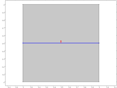
In the Model Builder window, under Component 1 (comp1) > Geometrical Optics (gop) click Material Discontinuity 1.
|
|
2
|
|
3
|
Select the Show boundary normal checkbox.
|
|
4
|
Locate the Coatings section. From the Thin dielectric films on boundary list, choose Add layers to surface.
|
|
5
|
Locate the Rays to Release section. From the Release reflected rays list, choose Never. It is still possible to analyze the reflectance of the coating based on the intensity of the transmitted rays, even if no reflected rays are actually released at the boundary.
|
|
1
|
|
2
|
|
3
|
|
4
|
|
1
|
|
2
|
|
3
|
|
4
|
|
1
|
|
2
|
|
3
|
|
4
|
|
5
|
|
6
|
|
7
|
Click
|
|
8
|
|
9
|
|
10
|
|
11
|
|
12
|
Click Replace.
|
|
1
|
|
2
|
|
3
|
|
4
|
|
5
|
|
1
|
|
2
|
|
3
|
|
4
|
|
5
|
|
6
|
|
7
|
Locate the Plot Settings section.
|
|
8
|
|
9
|
|
1
|
|
2
|
|
3
|
|
4
|
|
5
|
|
6
|
|
7
|
|
8
|
|
1
|
|
2
|
|
3
|
|
4
|
|
5
|
|
1
|
|
2
|
Go to the Add Study window.
|
|
3
|
Find the Studies subsection. In the Select Study tree, select Preset Studies for Selected Physics Interfaces > Ray Tracing.
|
|
4
|
Click the Add Study button in the window toolbar.
|
|
5
|
|
1
|
|
2
|
|
3
|
|
4
|
|
5
|
|
1
|
|
2
|
|
3
|
Select the Modify model configuration for study step checkbox.
|
|
4
|
In the tree, select Component 1 (comp1) > Geometrical Optics (gop) > Material Discontinuity 1 > Thin Dielectric Film 3.
|
|
5
|
Click
|
|
1
|
|
2
|
|
3
|
|
4
|
|
5
|
Locate the Legends section. In the table, enter the following settings:
|