|
|
|
|
kg/m3
|
||
|
kg/m3
|
||
|
1.76·10-5
|
||
|
5.808·10-14
|
m2
|
|
|
8.8·10-7
|
||
|
1
|
|
2
|
In the Select Physics tree, select Fluid Flow > Porous Media and Subsurface Flow > Multiphase Flow in Porous Media.
|
|
3
|
Click Add.
|
|
4
|
Click
|
|
5
|
|
6
|
Click
|
|
1
|
|
2
|
|
1
|
|
2
|
|
3
|
|
4
|
|
5
|
|
6
|
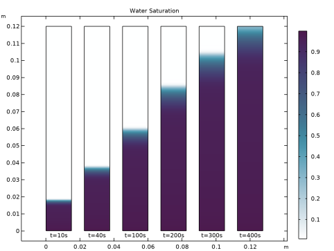
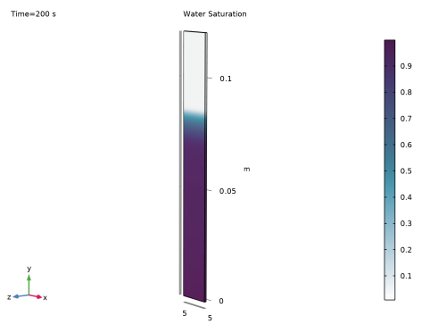
Click to expand the Smoothing section. In the Size of transition zone text field, type 0.2. This step function will be used to define the upper boundary condition for Darcy’s Law. It will ensure that the capillary pressure at the top is set to zero as soon as the paper is soaked with water.
|
|
1
|
|
2
|
|
3
|
|
4
|
|
5
|
Click
|
|
1
|
|
2
|
|
1
|
|
2
|
|
1
|
|
2
|
|
3
|
|
1
|
|
1
|
|
3
|
|
4
|
In the p0 text field, type -(phtr.pc_s2)*step1(s1)-rho_air*L0*g_const to calculate the hydrostatic pressure minus the capillary pressure at the upper boundary. The capillary pressure is set to zero when the paper strip is soaked with water by multiplying it with the smoothed step function defined earlier in the model.
|
|
5
|
|
6
|
In the Show More Options dialog, in the tree, select the checkbox for the node Physics > Advanced Physics Options.
|
|
7
|
Click OK.
|
|
8
|
|
9
|
|
10
|
|
1
|
In the Model Builder window, under Component 1 (comp1) click Phase Transport in Porous Media (phtr).
|
|
2
|
|
3
|
Select the Include gravity checkbox.
|
|
1
|
In the Model Builder window, under Component 1 (comp1) > Phase Transport in Porous Media (phtr) > Porous Medium 1 click Fluid 1.
|
|
2
|
|
3
|
|
4
|
|
5
|
|
6
|
|
7
|
|
1
|
In the Model Builder window, under Component 1 (comp1) > Phase Transport in Porous Media (phtr) click Initial Values 1.
|
|
2
|
|
3
|
|
1
|
|
2
|
|
3
|
Select the Phase s2 checkbox.
|
|
5
|
In the q0,s2 text field, type p_lm[kg/m/s]/th. Here p_lm is the Lagrange multiplier representing the flux at the boundary (see the section Notes About the COMSOL Implementation). It was introduced as an additional variable to solve for when the weak constraints were activated for this boundary in the Darcy’s Law interface. As the Lagrange multiplier does not take into account the thickness of the paper strip the flux has to be divided by it.
|
|
1
|
|
2
|
|
3
|
|
4
|
Locate the Homogenized Properties section. In the table, enter the following settings:
|
|
1
|
|
2
|
|
1
|
|
2
|
|
1
|
|
3
|
|
4
|
|
1
|
|
3
|
|
4
|
|
5
|
|
6
|
|
7
|
Click
|
|
8
|
|
1
|
|
2
|
|
3
|
|
1
|
|
2
|
|
3
|
|
4
|
|
5
|
|
6
|
|
7
|
Clear the Generate default plots checkbox. Predefined plots can be added after the computation using Result Templates.
|
|
8
|
|
1
|
|
2
|
Go to the Result Templates window.
|
|
3
|
In the tree, select Study 1/Solution 1 (sol1) > Phase Transport in Porous Media > Volume Fraction (phtr).
|
|
4
|
Click the Add Result Template button in the window toolbar.
|
|
5
|
|
1
|
|
2
|
|
3
|
|
4
|
|
5
|
Clear the Parameter indicator text field.
|
|
6
|
|
7
|
|
1
|
|
2
|
|
3
|
|
4
|
|
5
|
|
6
|
|
7
|
|
1
|
|
2
|
|
3
|
|
5
|
|
6
|
|
7
|
|
8
|
|
1
|
|
2
|
|
3
|
|
4
|
Click
|
|
1
|
|
2
|
|
3
|
|
4
|
|
5
|
|
6
|
|
1
|
|
2
|
|
3
|
|
4
|
|
1
|
|
2
|
|
1
|
|
1
|
|
1
|
|
2
|
|
4
|
Click
|
|
1
|
Go to the Table 1 window.
|
|
2
|
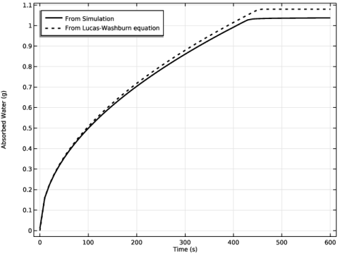
Click the Table Graph button in the window toolbar.
|
|
1
|
|
2
|
|
1
|
|
2
|
|
3
|
|
4
|
|
5
|
|
6
|
|
7
|
|
1
|
|
2
|
|
3
|
|
4
|
|
5
|
Locate the Plot Settings section.
|
|
6
|