
|
|
|


|
1
|
|
2
|
|
3
|
Click Add.
|
|
4
|
Click
|
|
5
|
|
6
|
Click
|
|
1
|
|
2
|
|
3
|
|
1
|
|
2
|
|
4
|
Select the Layers to the left checkbox.
|
|
5
|
Clear the Layers on bottom checkbox.
|
|
6
|
Click
|
|
1
|
|
2
|
On the object fin, select Boundary 4 only.
|
|
3
|
|
1
|
In the Model Builder window, under Component 1 (comp1) right-click Definitions and choose Variables.
|
|
2
|
|
3
|
Click
|
|
4
|
Browse to the model’s Application Libraries folder and double-click the file streamer_2d_variables.txt.
|
|
1
|
|
2
|
|
3
|
|
4
|
|
5
|
Locate the Units section. In the table, enter the following settings:
|
|
6
|
|
7
|
Locate the Plot Parameters section. In the table, enter the following settings:
|
|
1
|
|
2
|
|
3
|
|
4
|
Click to expand the Discretization section. From the Formulation list, choose Finite element (quadratic shape function).
|
|
1
|
|
2
|
|
3
|
|
4
|
|
5
|
|
6
|
|
1
|
|
2
|
|
3
|
Select the From mass constraint checkbox.
|
|
4
|
|
1
|
|
2
|
|
3
|
Select the Initial value from electroneutrality constraint checkbox.
|
|
4
|
|
5
|
Locate the Mobility and Diffusivity Expressions section. From the Specification list, choose Specify mobility, compute diffusivity.
|
|
6
|
|
1
|
|
2
|
|
3
|
|
4
|
|
5
|
From the list, choose Diagonal.
|
|
6
|
|
1
|
|
2
|
|
3
|
|
1
|
|
1
|
|
2
|
|
3
|
|
1
|
|
3
|
In the Settings window for Electron Density and Energy, locate the Electron Density and Energy section.
|
|
4
|
Select the Fix electron density checkbox.
|
|
5
|
|
1
|
|
2
|
|
3
|
From the list, choose User-controlled mesh.
|
|
1
|
|
2
|
|
3
|
|
4
|
|
1
|
|
2
|
|
3
|
|
4
|
|
6
|
Click to expand the Control Entities section. From the Smooth across removed control entities list, choose Off.
|
|
7
|
Click to expand the Reduce Element Skewness section.
|
|
1
|
|
3
|
|
4
|
|
5
|
|
6
|
|
7
|
|
1
|
|
3
|
|
4
|
|
1
|
|
2
|
|
3
|
|
4
|
Click
|
|
1
|
|
2
|
|
3
|
Select the Lock axis checkbox.
|
|
1
|
|
2
|
|
3
|
|
4
|
|
5
|
|
6
|
|
7
|
|
8
|
|
9
|
Click
|
|
1
|
|
2
|
|
3
|
Clear the Generate default plots checkbox.
|
|
4
|
|
1
|
|
2
|
|
1
|
|
2
|
|
3
|
|
4
|
|
1
|
|
2
|
|
3
|
|
4
|
|
5
|
|
1
|
|
2
|
|
3
|
|
4
|
|
5
|
|
6
|
|
7
|
|
1
|
|
2
|
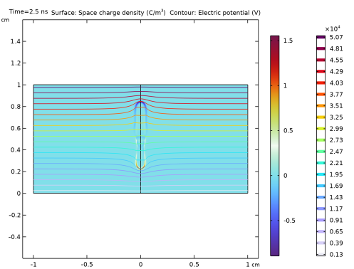
In the Settings window for 2D Plot Group, type Electric Potential and Space Charge Density in the Label text field.
|
|
3
|
|
4
|
|
1
|
|
2
|
|
3
|
|
4
|
|
5
|
|
1
|
In the Model Builder window, right-click Electric Potential and Space Charge Density and choose Contour.
|
|
2
|
|
3
|
|
4
|
|
1
|
|
2
|
|
3
|
|
1
|
|
2
|
|
3
|
|
4
|
|
5
|
|
6
|
|
1
|
|
2
|
|
3
|
|
4
|
|
1
|
|
2
|
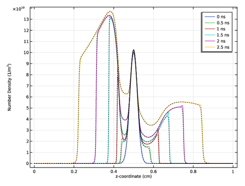
In the Settings window for 1D Plot Group, type Charged species number density in the Label text field.
|
|
3
|
|
4
|
Locate the Plot Settings section.
|
|
5
|
Select the y-axis label checkbox. In the associated text field, type Number Density (1/m<sup>3</sup>).
|
|
1
|
|
2
|
|
3
|
|
5
|
|
6
|
|
7
|
|
8
|
|
9
|
|
10
|
|
1
|
|
2
|
|
3
|
Clear the Show legends checkbox.
|
|
4
|
|
5
|
Click to expand the Coloring and Style section. Find the Line style subsection. From the Line list, choose Dotted.
|
|
6
|
|
1
|
|
2
|
|
3
|
|
4
|
|
5
|
|
6
|
|
7
|
|
8
|
|
1
|
|
3
|
|
4
|
|
5
|
|
6
|
|
7
|
|
8
|