PDF

Loudspeaker Spider Optimization
Introduction
The suspension of a loudspeaker is designed to keep the cone and dust cap in place and avoid any rocking movement of the voice coil. At low frequencies, where the displacement of the cone and dust cap is significant, the stiffness of the suspension varies along the stroke of the voice coil. The parameter is known as CMS(x). This variation, or nonlinearity, can play a significant role in the distortion created by the speaker.
This model performs shape optimization of the design of the spider, a thin membrane-like mechanical element, which is a part of the suspension of the loudspeaker. By changing the shape of the spider, it is possible to create a suspension system that behaves linearly (having a nearly constant stiffness CMS) all through the range of movement of the voice coil.
The model sets up constraints in the shape variables to make sure that the thickness of the spider remains constant. The final design features a loudspeaker suspension that behaves marginally nonlinearly through the voice coil stroke. This is an improvement over the traditional design, as nonlinearities in the mechanical behavior of the suspension introduce distortion when reproducing signals of large amplitude.
The geometry and simulation parameters are similar to those used in the tutorial Loudspeaker Driver — Frequency-Domain Analysis available in the Acoustics Module Application Library. More insight into the vibroacoustics analysis of that geometry can be gained by reading the documentation of that model.
This tutorial model illustrates:
Model Definition
The suspension of a loudspeaker is designed to keep the speaker cone in place and avoid any rocking movement of the voice coil. Figure 1 shows the main components of a loudspeaker, with the suspension system composed of the surround and the spider.
Figure 1: Geometry of the modeled loudspeaker driver.
When loudspeakers are excited at high frequencies, the displacement of the voice coil is relatively small. This means that at high frequencies, the compliance of the suspension along the path of the coil is almost constant. At low frequencies, the voice coil displacement becomes significant and the variation of the compliance, CMS(x), becomes more relevant. This variation of the compliance along the path of the coil is an undesired effect as it introduces distortion in the speaker. This effect is further explained in Figure 2.
Figure 2: Displacement of the voice coil (blue curves along the horizontal axis) when a high frequency (left) and low frequency (right) current travels through the voice coil (red curves along the vertical axis). At high frequencies, the displacement of the voice coil is small, meaning that the compliance remains almost constant through the movement, producing negligible distortion. At low frequencies, the large displacement of the coil means that the compliance will vary along the path, generating distortion in the displacement and the generated sound.
Although novelty designs exist, most loudspeakers use spiders made of a cloth membrane formed in a concentric zigzag pattern around the former. This pattern is included in the cloth to increase the compliance of the spider and make possible a large stroke of the voice coil, which is needed to produce sound at low frequencies. Figure 1 shows a traditional spider design.
The first study in the model analyzes a traditional design to include as a reference. In the second study, starting from a flat design, a shape optimization problem is defined to obtain a suspension system that behaves symmetrically through the stroke of the voice coil, but with a constraint on the compliance for the maximum displacement CMS.
Results and Discussion
The von Mises stress distribution of a traditional spider is shown in Figure 3. Note that both the surround and the spider show deformation, as both elements contribute to the total compliance of the suspension system.
Figure 3: von Mises stress of the traditional spider.
The shape optimization study starts with a flat design of the spider and improves the objective by changing the shape of the bottom boundary. The objective is to minimize the difference between the compliance of the suspension system from an ideal linear suspension system. The change of the bottom boundary is carried over to the top boundary using a General Extrusion operator. The deformation of the top boundary accounts for the displacement and change in the normal direction of the bottom surface to guarantee that the thickness of the spider remains constant.
Figure 4 shows the relative normal boundary displacement and the von Mises stress of the optimized design.
Figure 5 shows the force versus displacement and compliance curves of the traditional design, an idealized design, and the optimized design.
Figure 4: Relative normal displacement of the optimized design.
Figure 5: Force versus displacement and compliance curve of a traditional design (blue dots), an ideal suspension (gray line) and the optimized design (green dots). Note how the behavior of the traditional design deviates from the ideal behavior as the displacement increases.
Figure 6: Revolved geometry of the optimized design.
The von Mises stress distribution of the revolved optimized design is shown in Figure 6.
This model demonstrates an efficient approach to optimize nonlinear structural problems where the performance through the different points of loading is also relevant to measure the overall performance. It also demonstrates how optimization can be used to obtain novel designs using traditional materials and manufacturing techniques, significantly improving the performance.
Notes About the COMSOL Implementation
Using a Single Component and Physics to Represent Two Designs
The model uses different boundary conditions to represent two designs using a single geometry and the same physics. When using this type of approach, it is important to pay attention to the validity of the approach for the analysis of interest. In this case, for example, it is important to note that the approach is only valid for analyzing the static stiffness of the model, as the mass of the two designs will be included as moving masses if a frequency domain analysis was used instead. This model is also very light and runs fast, but the computational implication of including part of the model that is not relevant for the analysis should be considered in larger models.
Using General Extrusion
A general extrusion coupling operator is used to carry over the shape changes from the bottom boundary to the top boundary. A set of variables under the Angle Variables group compute the change in the normal direction of the bottom boundary to make sure that the thickness remains constant through the spider domain.
Using Domain Probes to Compute the Optimization Objectives
The objective of the optimization is based on a domain probe. The displacement and stiffness are computed through this domain probe and are used in the optimization objective.
Application Library path: Optimization_Module/Shape_Optimization/loudspeaker_spider_optimization
Modeling Instructions
From the File menu, choose New.
New
In the New window, click  Model Wizard.
Model Wizard
1
In the Model Wizard window, click  2D Axisymmetric.
2
In the Select Physics tree, select Structural Mechanics > Solid Mechanics (solid).
3
Click Add.
4
Click  Study.
5
In the Select Study tree, select General Studies > Stationary.
6
Geometry 1
1
In the Model Builder window, under Component 1 (comp1) click Geometry 1.
2
In the Settings window for Geometry, locate the Units section.
3
From the Length unit list, choose mm.
4
In the Geometry toolbar, click Insert Sequence and choose Insert Sequence.
5
6
In the Geometry toolbar, click  Build All.
Global Definitions
Parameters 1
1
In the Model Builder window, under Global Definitions click Parameters 1.
2
In the Settings window for Parameters, locate the Parameters section.
3
Click  Load from File.
4
Definitions
Control Function 1 (cfunc1)
1
In the Definitions toolbar, click  Control Variables and choose Control Function.
2
In the Settings window for Control Function, locate the Input section.
3
In the xend text field, type Fmax.
4
From the Extrapolation list, choose Linear.
5
Locate the Output section. In the fmax text field, type 2*susp_comp0.
6
From the End boundary condition list, choose Dirichlet.
7
In the f(xend) text field, type susp_comp0.
8
In the c0 text field, type susp_comp0.
9
Locate the Control Variable Discretization section. From the Control type list, choose Piecewise Bernstein polynomial.
10
Locate the Units section. Click  Define Output Unit.
11
In the Function quantity table, enter the following settings:
12
Click  Select Input Quantity.
13
In the Physical Quantity dialog, select General > Force (N) in the tree.
14
Definitions (comp1)
Optimization Objective
1
In the Model Builder window, under Component 1 (comp1) right-click Definitions and choose Variables.
2
In the Settings window for Variables, type Optimization Objective in the Label text field.
3
Locate the Variables section. In the table, enter the following settings:
The 1[m/N] factor serves to remove the unit from the objective.
Angle Variables
1
Right-click Definitions and choose Variables.
2
In the Settings window for Variables, type Angle Variables in the Label text field.
3
Locate the Geometric Entity Selection section. From the Geometric entity level list, choose Boundary.
4
5
Locate the Variables section. In the table, enter the following settings:
Domain Probe 1 (dom1)
1
In the Definitions toolbar, click  Probes and choose Domain Probe.
2
In the Settings window for Domain Probe, type susp_disp in the Variable name text field.
3
Locate the Source Selection section. From the Selection list, choose Voice Coil.
4
Locate the Expression section. In the Expression text field, type w.
5
Select the Description checkbox. In the associated text field, type Displacement.
Domain Probe 2 (dom2)
1
In the Definitions toolbar, click  Probes and choose Domain Probe.
2
In the Settings window for Domain Probe, type susp_stiff in the Variable name text field.
3
Locate the Source Selection section. From the Selection list, choose Voice Coil.
4
Locate the Expression section. In the Expression text field, type F0*Fsign/w.
5
From the Table and plot unit list, choose N/mm.
6
Select the Description checkbox. In the associated text field, type Suspension stiffness.
General Extrusion 1 (genext1)
1
In the Definitions toolbar, click  Nonlocal Couplings and choose General Extrusion.
2
In the Settings window for General Extrusion, locate the Source Selection section.
3
From the Geometric entity level list, choose Boundary.
4
5
Locate the Destination Map section. In the r-expression text field, type Rg.
6
In the z-expression text field, type -49.7[mm].
7
Locate the Source section. From the Source frame list, choose Geometry  (Rg, PHIg, Zg).
Component 1 (comp1)
Free Shape Domain 1
1
In the Physics toolbar, click  Optimization and choose Shape Optimization.
2
In the Settings window for Free Shape Domain, locate the Domain Selection section.
3
From the Selection list, choose Shape Optimization.
Free Shape Boundary 1
1
In the Shape Optimization toolbar, click  Free Shape Boundary.
2
3
In the Settings window for Free Shape Boundary, locate the Control Variable Settings section.
4
From the dmax list, choose User defined.
5
6
Locate the Filtering section. From the Rmin list, choose User defined.
7
Prescribed Deformation 1
1
In the Model Builder window, right-click Component 1 (comp1) and choose Deformed Geometry > Prescribed Deformation.
2
In the Settings window for Prescribed Deformation, locate the Geometric Entity Selection section.
3
From the Geometric entity level list, choose Boundary.
4
5
Locate the Prescribed Deformation section. Specify the dx vector as
6
Right-click Prescribed Deformation 1 and choose Browse Materials.
Material Browser
1
In the Material Browser window, click  Import Material Library.
2
From the Application Libraries root, browse to the folder Acoustics_Module/Electroacoustic_Transducers and double-click the file loudspeaker_driver_materials.mph.
3
Add Material
1
In the Materials toolbar, click  Add Material to open the Add Material window.
2
Go to the Add Material window.
3
In the tree, select loudspeaker driver materials > Composite.
4
Click the Add to Component button in the window toolbar.
Materials
Composite (mat1)
1
In the Settings window for Material, locate the Geometric Entity Selection section.
2
From the Selection list, choose Composite.
Add Material
1
Go to the Add Material window.
2
In the tree, select loudspeaker driver materials > Cloth.
3
Click the Add to Component button in the window toolbar.
Materials
Cloth (mat2)
1
In the Settings window for Material, locate the Geometric Entity Selection section.
2
From the Selection list, choose Cloth.
Add Material
1
Go to the Add Material window.
2
In the tree, select loudspeaker driver materials > Foam.
3
Click the Add to Component button in the window toolbar.
Materials
Foam (mat3)
1
In the Settings window for Material, locate the Geometric Entity Selection section.
2
From the Selection list, choose Foam.
Add Material
1
Go to the Add Material window.
2
In the tree, select loudspeaker driver materials > Coil.
3
Click the Add to Component button in the window toolbar.
Materials
Coil (mat4)
1
In the Settings window for Material, locate the Geometric Entity Selection section.
2
From the Selection list, choose Voice Coil.
Add Material
1
Go to the Add Material window.
2
In the tree, select loudspeaker driver materials > Glass Fiber.
3
Click the Add to Component button in the window toolbar.
4
In the Materials toolbar, click  Add Material to close the Add Material window.
Materials
Glass Fiber (mat5)
1
In the Settings window for Material, locate the Geometric Entity Selection section.
2
From the Selection list, choose Former.
Solid Mechanics (solid)
1
In the Model Builder window, under Component 1 (comp1) click Solid Mechanics (solid).
2
In the Settings window for Solid Mechanics, locate the Domain Selection section.
3
From the Selection list, choose Structural Domains.
Body Load 1
1
In the Physics toolbar, click  Domains and choose Body Load.
2
In the Settings window for Body Load, locate the Domain Selection section.
3
From the Selection list, choose Voice Coil.
4
Locate the Force section. From the Load type list, choose Total force.
5
Specify the Ftot vector as
Fixed Constraint 1
1
In the Physics toolbar, click  Boundaries and choose Fixed Constraint.
2
In the Settings window for Fixed Constraint, locate the Boundary Selection section.
3
From the Selection list, choose Fixed Boundaries 1.
Fixed Constraint 2
1
In the Physics toolbar, click  Boundaries and choose Fixed Constraint.
2
In the Settings window for Fixed Constraint, locate the Boundary Selection section.
3
From the Selection list, choose Fixed Boundaries 2.
Mesh 1
Mapped 1
1
In the Mesh toolbar, click  Mapped.
2
In the Settings window for Mapped, locate the Domain Selection section.
3
From the Geometric entity level list, choose Domain.
4
From the Selection list, choose Structural Domains.
Size 1
1
Right-click Mapped 1 and choose Size.
2
In the Settings window for Size, locate the Element Size section.
3
Click the Custom button.
4
Locate the Element Size Parameters section.
5
Select the Maximum element size checkbox. In the associated text field, type mesh_size.
Distribution 1
1
In the Model Builder window, right-click Mapped 1 and choose Distribution.
2
In the Settings window for Distribution, locate the Boundary Selection section.
3
From the Selection list, choose Fixed Boundaries 1.
4
Locate the Distribution section. In the Number of elements text field, type 2.
Distribution 2
1
Right-click Mapped 1 and choose Distribution.
2
In the Settings window for Distribution, locate the Boundary Selection section.
3
From the Selection list, choose Fixed Boundaries 2.
4
Locate the Distribution section. In the Number of elements text field, type 2.
5
Click  Build All.
Free Triangular 1
1
In the Mesh toolbar, click  Free Triangular.
2
In the Settings window for Free Triangular, click  Build All.
Study 1 - Traditional Design
1
In the Model Builder window, click Study 1.
2
In the Settings window for Study, type Study 1 - Traditional Design in the Label text field.
Step 1: Stationary
1
In the Model Builder window, under Study 1 - Traditional Design click Step 1: Stationary.
2
In the Settings window for Stationary, locate the Study Settings section.
3
Select the Include geometric nonlinearity checkbox.
4
Click to expand the Results While Solving section. From the Probes list, choose None.
5
Locate the Physics and Variables Selection section. Select the Modify model configuration for study step checkbox.
6
In the tree, select Component 1 (comp1) > Solid Mechanics (solid), Controls spatial frame > Fixed Constraint 2.
7
Click  Disable.
8
Click to expand the Study Extensions section. Select the Auxiliary sweep checkbox.
9
From the Sweep type list, choose All combinations.
10
11
12
13
14
In the Study toolbar, click  Compute.
Results
Study 1 - Traditional Design/Solution 1 (sol1)
In the Model Builder window, expand the Results > Datasets node, then click Study 1 - Traditional Design/Solution 1 (sol1).
Selection
1
In the Results toolbar, click  Attributes and choose Selection.
2
In the Settings window for Selection, locate the Geometric Entity Selection section.
3
From the Geometric entity level list, choose Domain.
4
Deformed Geometry, Shape Optimization
1
In the Model Builder window, under Results, Ctrl-click to select Shape Optimization and Deformed Geometry.
2
Stress (solid), Stress, 3D (solid)
1
In the Model Builder window, under Results, Ctrl-click to select Stress (solid) and Stress, 3D (solid).
2
Traditional Design Results
In the Settings window for Group, type Traditional Design Results in the Label text field.
Add Study
1
In the Home toolbar, click  Add Study to open the Add Study window.
2
Go to the Add Study window.
3
Find the Studies subsection. In the Select Study tree, select Empty Study.
4
Click the Add Study button in the window toolbar.
5
In the Home toolbar, click  Add Study to close the Add Study window.
Study 1 - Traditional Design
Step 1: Stationary
In the Model Builder window, under Study 1 - Traditional Design right-click Step 1: Stationary and choose Copy.
Study 2
In the Model Builder window, right-click Study 2 and choose Paste Stationary.
Shape Optimization
1
In the Study toolbar, click  Optimization and choose Shape Optimization.
2
In the Settings window for Shape Optimization, locate the Objective Function section.
3
From the Solution list, choose Maximum of objectives.
4
Locate the Optimization Solver section. Clear the Move limits checkbox.
5
Locate the Objective Function section. In the table, enter the following settings:
6
Click to expand the Output section. From the Probes list, choose None.
Step 1: Stationary
1
In the Model Builder window, click Step 1: Stationary.
2
In the Settings window for Stationary, locate the Physics and Variables Selection section.
3
In the tree, select Component 1 (comp1) > Solid Mechanics (solid), Controls spatial frame > Fixed Constraint 1.
4
Click  Disable.
5
In the tree, select Component 1 (comp1) > Solid Mechanics (solid), Controls spatial frame > Fixed Constraint 2.
6
Click  Enable.
7
Locate the Study Extensions section. In the table, enter the following settings:
8
In the Model Builder window, click Study 2.
9
In the Settings window for Study, type Study 2 - Optimization in the Label text field.
10
In the Study toolbar, click  Get Initial Value.
Results
Study 2 - Optimization/Solution 2 (sol2)
In the Model Builder window, under Results > Datasets click Study 2 - Optimization/Solution 2 (sol2).
Selection
1
In the Results toolbar, click  Attributes and choose Selection.
2
In the Settings window for Selection, locate the Geometric Entity Selection section.
3
From the Geometric entity level list, choose Domain.
4
Arrow Line 1
1
In the Model Builder window, expand the Results > Shape Optimization node, then click Arrow Line 1.
2
In the Settings window for Arrow Line, locate the Arrow Positioning section.
3
From the Placement list, choose Gauss points.
Deformed Geometry, Shape Optimization, Stress (solid) 1, Stress, 3D (solid) 1
1
In the Model Builder window, under Results, Ctrl-click to select Stress (solid) 1, Stress, 3D (solid) 1, Shape Optimization, and Deformed Geometry.
2
Optimization Results
In the Settings window for Group, type Optimization Results in the Label text field.
Study 2 - Optimization
Shape Optimization
1
In the Model Builder window, under Study 2 - Optimization click Shape Optimization.
2
In the Settings window for Shape Optimization, locate the Output section.
3
Select the Plot checkbox.
4
5
In the Study toolbar, click  Compute.
Results
Force vs. Displacement
1
In the Results toolbar, click  1D Plot Group.
2
In the Settings window for 1D Plot Group, type Force vs. Displacement in the Label text field.
3
Locate the Plot Settings section.
4
Select the x-axis label checkbox. In the associated text field, type Displacement (mm).
5
Select the y-axis label checkbox. In the associated text field, type Applied Force (N).
6
Click to expand the Title section. From the Title type list, choose Label.
7
Locate the Legend section. From the Position list, choose Lower right.
Global 1
1
Right-click Force vs. Displacement and choose Global.
2
In the Settings window for Global, locate the y-Axis Data section.
3
4
Locate the x-Axis Data section. From the Axis source data list, choose All solutions.
5
From the Parameter list, choose Expression.
6
In the Expression text field, type susp_disp.
7
Click to expand the Legends section. From the Legends list, choose Manual.
8
9
Click to expand the Coloring and Style section. Find the Line style subsection. From the Line list, choose None.
10
Find the Line markers subsection. From the Marker list, choose Circle.
11
In the Force vs. Displacement toolbar, click  Plot.
Global 2
1
Right-click Global 1 and choose Duplicate.
2
In the Settings window for Global, locate the Data section.
3
From the Dataset list, choose Study 2 - Optimization/Solution 2 (sol2).
4
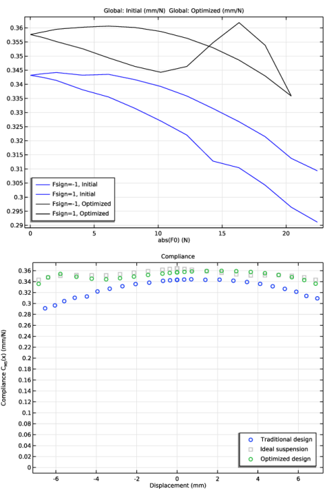
Locate the y-Axis Data section. In the table, enter the following settings:
5
Locate the Coloring and Style section. From the Color list, choose Gray.
6
Find the Line markers subsection. From the Marker list, choose Square.
7
Locate the Legends section. In the table, enter the following settings:
Global 3
1
In the Model Builder window, under Results > Force vs. Displacement right-click Global 1 and choose Duplicate.
2
In the Settings window for Global, locate the Data section.
3
From the Dataset list, choose Study 2 - Optimization/Solution 2 (sol2).
4
Locate the Legends section. In the table, enter the following settings:
5
In the Force vs. Displacement toolbar, click  Plot.
The image should look like Figure 5.
Compliance
1
In the Model Builder window, right-click Force vs. Displacement and choose Duplicate.
2
In the Settings window for 1D Plot Group, type Compliance in the Label text field.
3
Locate the Plot Settings section. In the y-axis label text field, type Compliance C<sub>MS</sub>(x) (mm/N).
Global 1
1
In the Model Builder window, expand the Compliance node, then click Global 1.
2
In the Settings window for Global, locate the y-Axis Data section.
3
Global 2
1
In the Model Builder window, click Global 2.
2
In the Settings window for Global, locate the y-Axis Data section.
3
Global 3
1
In the Model Builder window, click Global 3.
2
In the Settings window for Global, locate the y-Axis Data section.
3
4
In the Compliance toolbar, click  Plot.
Annotation 1
1
In the Model Builder window, right-click Compliance and choose Annotation.
2
In the Settings window for Annotation, locate the Coloring and Style section.
3
Clear the Show point checkbox.
4
In the Compliance toolbar, click  Plot.
The image should look like Figure 5.
Stress, 3D (solid)
In the Model Builder window, expand the Results > Traditional Design Results > Stress, 3D (solid) node.
Deformation
1
In the Model Builder window, expand the Results > Traditional Design Results > Stress, 3D (solid) > Surface 1 node.
2
Right-click Deformation and choose Delete.
Stress, 3D (solid) 1
In the Model Builder window, expand the Results > Optimization Results > Stress, 3D (solid) 1 node.
Deformation
1
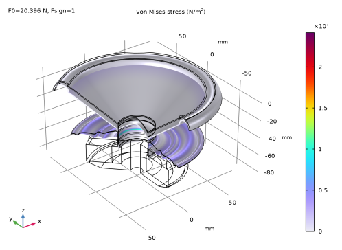
In the Model Builder window, expand the Results > Optimization Results > Stress, 3D (solid) 1 > Surface 1 node.
2
Right-click Deformation and choose Delete.
Surface 1
1
In the Stress, 3D (solid) 1 toolbar, click  Plot.
The image should look like Figure 6.
Geometry Modeling Instructions
If you want to create the geometry yourself, follow these steps.
From the File menu, choose New.
New
In the New window, click  Blank Model.
Add Component
In the Home toolbar, click  Add Component and choose 2D Axisymmetric.
Geometry 1
Circle 1 (c1)
1
In the Geometry toolbar, click  Circle.
2
In the Settings window for Circle, locate the Size and Shape section.
3
In the Radius text field, type 130[mm].
4
Click to expand the Layers section. In the table, enter the following settings:
Circle 2 (c2)
1
In the Geometry toolbar, click  Circle.
2
In the Settings window for Circle, locate the Size and Shape section.
3
In the Radius text field, type 8[mm].
4
In the Sector angle text field, type 180.
5
Locate the Position section. In the r text field, type 74[mm].
6
Locate the Layers section. In the table, enter the following settings:
Delete Entities 1 (del1)
1
In the Model Builder window, right-click Geometry 1 and choose Delete Entities.
2
On the object c2, select Boundaries 2–4 only.
3
In the Settings window for Delete Entities, locate the Selections of Resulting Entities section.
4
Select the Resulting objects selection checkbox.
Rectangle 1 (r1)
1
In the Geometry toolbar, click  Rectangle.
2
In the Settings window for Rectangle, locate the Size and Shape section.
3
In the Width text field, type 70[mm].
4
In the Height text field, type 1[mm].
5
Locate the Position section. In the r text field, type 80.5[mm].
6
In the z text field, type -1[mm].
Difference 1 (dif1)
1
In the Geometry toolbar, click  Booleans and Partitions and choose Difference.
2
3
In the Settings window for Difference, locate the Difference section.
4
Click to select the  Activate Selection toggle button for Objects to subtract.
5
Rectangle 2 (r2)
1
In the Geometry toolbar, click  Rectangle.
2
In the Settings window for Rectangle, locate the Size and Shape section.
3
In the Width text field, type 42[mm].
4
In the Height text field, type 35[mm].
5
Locate the Position section. In the r text field, type 6[mm].
6
In the z text field, type -87[mm].
Rectangle 3 (r3)
1
In the Geometry toolbar, click  Rectangle.
2
In the Settings window for Rectangle, locate the Size and Shape section.
3
In the Width text field, type 35.5[mm].
4
In the Height text field, type 20[mm].
5
Locate the Position section. In the r text field, type 15.5[mm].
6
In the z text field, type -80[mm].
Rectangle 4 (r4)
1
In the Geometry toolbar, click  Rectangle.
2
In the Settings window for Rectangle, locate the Size and Shape section.
3
In the Width text field, type 1.2[mm].
4
In the Height text field, type 8[mm].
5
Locate the Position section. In the r text field, type 17.8[mm].
6
In the z text field, type -60[mm].
Rectangle 5 (r5)
1
In the Geometry toolbar, click  Rectangle.
2
In the Settings window for Rectangle, locate the Size and Shape section.
3
In the Width text field, type 26[mm].
4
In the Height text field, type 20[mm].
5
Locate the Position section. In the r text field, type 25[mm].
6
In the z text field, type -80[mm].
Polygon 1 (pol1)
1
In the Geometry toolbar, click  Polygon.
2
In the Settings window for Polygon, locate the Coordinates section.
3
From the Data source list, choose Vectors.
4
In the r text field, type 48[mm] 36[mm] 36[mm] 48[mm].
5
In the z text field, type -82[mm] -87[mm] -87[mm] -87[mm].
Difference 2 (dif2)
1
In the Geometry toolbar, click  Booleans and Partitions and choose Difference.
2
3
In the Settings window for Difference, locate the Difference section.
4
Click to select the  Activate Selection toggle button for Objects to subtract.
5
Select the objects pol1, r3, and r4 only.
6
Locate the Selections of Resulting Entities section. Select the Resulting objects selection checkbox.
Rectangle 6 (r6)
1
In the Geometry toolbar, click  Rectangle.
2
In the Settings window for Rectangle, locate the Size and Shape section.
3
In the Width text field, type 0.2[mm].
4
In the Height text field, type 25[mm].
5
Locate the Position section. In the r text field, type 18.2[mm].
6
In the z text field, type -64[mm].
7
Click to expand the Layers section. In the table, enter the following settings:
8
Clear the Layers on bottom checkbox.
9
Select the Layers on top checkbox.
Rectangle 7 (r7)
1
In the Geometry toolbar, click  Rectangle.
2
In the Settings window for Rectangle, locate the Size and Shape section.
3
In the Width text field, type 0.6[mm].
4
In the Height text field, type 9.4[mm].
5
Locate the Position section. In the r text field, type 18.2[mm].
6
In the z text field, type -60.7[mm].
Rectangle 8 (r8)
1
In the Geometry toolbar, click  Rectangle.
2
In the Settings window for Rectangle, locate the Size and Shape section.
3
In the Width text field, type 4.6[mm].
4
In the Height text field, type 0.4[mm].
5
Locate the Position section. In the r text field, type 18.4[mm].
6
In the z text field, type -44.5[mm].
Rectangle 9 (r9)
1
In the Geometry toolbar, click  Rectangle.
2
In the Settings window for Rectangle, locate the Size and Shape section.
3
In the Width text field, type 7[mm].
4
In the Height text field, type 0.4[mm].
5
Locate the Position section. In the r text field, type 59[mm].
6
In the z text field, type -44.5[mm].
Polygon 2 (pol2)
1
In the Geometry toolbar, click  Polygon.
2
In the Settings window for Polygon, locate the Coordinates section.
3
From the Data source list, choose Vectors.
4
In the r text field, type 23[mm] 26[mm] 26[mm] 32[mm] 32[mm] 38[mm] 38[mm] 44[mm] 44[mm] 50[mm] 50[mm] 56[mm] 56[mm] 59[mm] 59[mm] 59[mm] 59[mm] 56[mm] 56[mm] 50[mm] 50[mm] 44[mm] 44[mm] 38[mm] 38[mm] 32[mm] 32[mm] 26[mm] 26[mm] 23[mm] 23[mm] 23[mm].
5
In the z text field, type -44.1[mm] -42.1[mm] -42.1[mm] -46.1[mm] -46.1[mm] -42.1[mm] -42.1[mm] -46.1[mm] -46.1[mm] -42.1[mm] -42.1[mm] -46.1[mm] -46.1[mm] -44.1[mm] -44.1[mm] -44.5[mm] -44.5[mm] -46.5[mm] -46.5[mm] -42.5[mm] -42.5[mm] -46.5[mm] -46.5[mm] -42.5[mm] -42.5[mm] -46.5[mm] -46.5[mm] -42.5[mm] -42.5[mm] -44.5[mm] -44.5[mm] -44.1.
Union 1 (uni1)
1
In the Geometry toolbar, click  Booleans and Partitions and choose Union.
2
Select the objects pol2, r8, and r9 only.
3
In the Settings window for Union, locate the Selections of Resulting Entities section.
4
Select the Resulting objects selection checkbox.
5
Locate the Union section. Clear the Keep interior boundaries checkbox.
Polygon 3 (pol3)
1
In the Geometry toolbar, click  Polygon.
2
In the Settings window for Polygon, locate the Coordinates section.
3
From the Data source list, choose Vectors.
4
In the r text field, type 18.4[mm] 66[mm] 66[mm] 67.5[mm] 67.5[mm] 18.4[mm] 18.4[mm] 18.4[mm].
5
In the z text field, type -39[mm] 0 0 0 0 -40.26[mm] -40.26[mm] -39[mm].
Quadratic Bézier 1 (qb1)
1
In the Geometry toolbar, click  More Primitives and choose Quadratic Bézier.
2
In the Settings window for Quadratic Bézier, locate the Control Points section.
3
In row 1, set r to -18.2[mm].
4
In row 3, set r to 18.2[mm].
5
In row 1, set z to -39[mm].
6
In row 2, set z to -23.5[mm].
7
In row 3, set z to -39[mm].
8
Locate the Weights section. In the 2 text field, type 1.
Line Segment 1 (ls1)
1
In the Geometry toolbar, click  More Primitives and choose Line Segment.
2
In the Settings window for Line Segment, locate the Starting Point section.
3
From the Specify list, choose Coordinates.
4
Locate the Endpoint section. From the Specify list, choose Coordinates.
5
Locate the Starting Point section. In the r text field, type 18.2[mm].
6
Locate the Endpoint section. In the r text field, type 18.2[mm].
7
Locate the Starting Point section. In the z text field, type -39[mm].
8
Locate the Endpoint section. In the z text field, type -40.26[mm].
Quadratic Bézier 2 (qb2)
1
In the Geometry toolbar, click  More Primitives and choose Quadratic Bézier.
2
In the Settings window for Quadratic Bézier, locate the Control Points section.
3
In row 1, set r to 18.2[mm].
4
In row 3, set r to -18.2[mm].
5
In row 1, set z to -40.26[mm].
6
In row 2, set z to -24.26[mm].
7
In row 3, set z to -40.26[mm].
8
Locate the Weights section. In the 2 text field, type 1.
Line Segment 2 (ls2)
1
In the Geometry toolbar, click  More Primitives and choose Line Segment.
2
In the Settings window for Line Segment, locate the Starting Point section.
3
From the Specify list, choose Coordinates.
4
Locate the Endpoint section. From the Specify list, choose Coordinates.
5
Locate the Starting Point section. In the r text field, type -18.2[mm].
6
Locate the Endpoint section. In the r text field, type -18.2[mm].
7
Locate the Starting Point section. In the z text field, type -40.26[mm].
8
Locate the Endpoint section. In the z text field, type -39[mm].
Convert to Solid 1 (csol1)
1
In the Geometry toolbar, click  Conversions and choose Convert to Solid.
2
Select the objects ls1, ls2, qb1, and qb2 only.
Line Segment 3 (ls3)
1
In the Geometry toolbar, click  More Primitives and choose Line Segment.
2
In the Settings window for Line Segment, locate the Starting Point section.
3
From the Specify list, choose Coordinates.
4
In the z text field, type -52[mm].
5
Locate the Endpoint section. From the Specify list, choose Coordinates.
6
In the r text field, type sqrt((115[mm])^2 - (52[mm])^2).
7
In the z text field, type -52[mm].
8
Locate the Selections of Resulting Entities section. Select the Resulting objects selection checkbox.
Union 2 (uni2)
1
In the Geometry toolbar, click  Booleans and Partitions and choose Union.
2
Click in the Graphics window and then press Ctrl+A to select all objects.
Delete Entities 2 (del2)
1
Right-click Geometry 1 and choose Delete Entities.
2
On the object uni2, select Boundaries 13, 19, 33, and 45 only.
Fillet 1 (fil1)
1
In the Geometry toolbar, click  Fillet.
2
On the object del2, select Points 14, 15, 35, and 36 only.
3
In the Settings window for Fillet, locate the Radius section.
4
In the Radius text field, type 0.2[mm].
Form Union (fin)
1
In the Model Builder window, click Form Union (fin).
2
In the Settings window for Form Union/Assembly, locate the Form Union/Assembly section.
3
From the Repair tolerance list, choose Relative.
Ignore Vertices 1 (igv1)
1
In the Geometry toolbar, click  Virtual Operations and choose Ignore Vertices.
2
On the object fin, select Points 18, 26, and 33 only.
3
In the Geometry toolbar, click  Build All.