|
|
|


|
1
|
|
2
|
In the Select Physics tree, select Fluid Flow > Nonisothermal Flow > Nonisothermal Pipe Flow (nipfl).
|
|
3
|
Click Add.
|
|
4
|
In the Select Physics tree, select Mathematics > PDE Interfaces > Lower Dimensions > Coefficient Form Edge PDE (ce).
|
|
5
|
Click Add.
|
|
6
|
|
7
|
In the Dependent variables (1) table, enter the following settings:
|
|
8
|
Click
|
|
9
|
|
10
|
|
11
|
Click OK.
|
|
12
|
|
13
|
|
14
|
|
15
|
Click OK.
|
|
16
|
|
17
|
|
18
|
Click
|
|
1
|
|
2
|
Browse to the model’s Application Libraries folder and double-click the file district_heating_optimization_geom_sequence.mph.
|
|
3
|
|
4
|
|
5
|
|
6
|
|
1
|
|
2
|
|
1
|
|
2
|
|
3
|
|
4
|
Browse to the model’s Application Libraries folder and double-click the file district_heating_optimization_parameters.txt.
|
|
1
|
|
2
|
Go to the Add Material window.
|
|
3
|
|
4
|
Click the Add to Component button in the window toolbar.
|
|
5
|
|
1
|
|
2
|
|
3
|
|
4
|
|
5
|
|
6
|
Locate the Discretization section. From the Shape function type list, choose Discontinuous Lagrange.
|
|
7
|
|
8
|
|
9
|
|
10
|
|
1
|
|
2
|
|
3
|
|
4
|
|
5
|
|
6
|
Locate the Discretization section. From the Shape function type list, choose Discontinuous Lagrange.
|
|
7
|
|
8
|
|
9
|
|
10
|
|
1
|
|
2
|
|
3
|
|
4
|
|
1
|
|
2
|
|
3
|
|
4
|
|
5
|
|
1
|
|
2
|
|
3
|
|
4
|
|
1
|
|
2
|
|
3
|
|
4
|
|
1
|
|
2
|
|
3
|
|
4
|
|
5
|
|
1
|
|
2
|
|
3
|
|
4
|
|
1
|
|
2
|
|
3
|
|
1
|
|
2
|
|
3
|
|
4
|
|
1
|
|
2
|
|
3
|
|
4
|
|
5
|
|
1
|
|
2
|
|
3
|
|
4
|
|
1
|
|
2
|
|
3
|
|
4
|
|
5
|
|
1
|
|
2
|
|
3
|
|
4
|
|
1
|
|
2
|
|
1
|
|
2
|
|
3
|
|
4
|
Locate the Definition section. In the Expression text field, type 2202+(2922-2202)*(x-0.032)/(0.4-0.032).
|
|
5
|
|
1
|
|
2
|
|
3
|
|
4
|
|
5
|
Locate the Variables section. In the table, enter the following settings:
|
|
1
|
|
2
|
|
3
|
|
4
|
Locate the Variables section. In the table, enter the following settings:
|
|
1
|
|
2
|
|
3
|
|
4
|
Locate the Variables section. In the table, enter the following settings:
|
|
1
|
|
2
|
|
3
|
|
4
|
Locate the Variables section. In the table, enter the following settings:
|
|
1
|
|
2
|
|
3
|
Locate the Variables section. In the table, enter the following settings:
|
|
1
|
In the Model Builder window, under Component 1 (comp1) > Nonisothermal Pipe Flow (nipfl) click Pipe Properties 1.
|
|
2
|
|
3
|
From the list, choose Circular.
|
|
4
|
|
1
|
|
2
|
|
3
|
|
1
|
|
2
|
|
3
|
|
1
|
|
2
|
|
3
|
|
4
|
|
1
|
|
2
|
|
3
|
|
4
|
|
1
|
|
2
|
|
3
|
|
4
|
|
1
|
|
2
|
|
3
|
|
4
|
|
1
|
|
2
|
|
3
|
|
1
|
|
2
|
|
3
|
|
1
|
|
2
|
In the Settings window for Coefficient Form Edge PDE, type Average Consumer Power in the Label text field.
|
|
3
|
|
1
|
In the Model Builder window, under Component 1 (comp1) > Average Consumer Power (ce) click Coefficient Form PDE 1.
|
|
2
|
|
3
|
|
4
|
|
5
|
|
1
|
|
2
|
|
3
|
|
1
|
|
2
|
|
3
|
|
1
|
In the Model Builder window, expand the Study 1: Initial Design > Solver Configurations > Solution 1 (sol1) node.
|
|
2
|
|
3
|
|
4
|
|
5
|
|
6
|
In the Add dialog, in the Variables list, choose Control Variable Field (comp1.bypass), Control Variable Field (comp1.consumers), Control Variable Field (comp1.pipeControl), and Temperature (comp1.T).
|
|
7
|
Click OK.
|
|
8
|
|
9
|
|
10
|
|
11
|
In the Add dialog, in the Variables list, choose Control Variable Field (comp1.bypass), Control Variable Field (comp1.consumers), Dependent Variable P (comp1.P), and Control Variable Field (comp1.pipeControl).
|
|
12
|
Click OK.
|
|
13
|
In the Model Builder window, under Study 1: Initial Design > Solver Configurations > Solution 1 (sol1) > Stationary Solver 1 > Segregated 1 click Segregated Step.
|
|
14
|
|
15
|
Locate the General section. In the Variables list, choose Dependent Variable P (comp1.P) and Temperature (comp1.T).
|
|
16
|
|
17
|
|
1
|
|
2
|
|
3
|
|
4
|
|
1
|
|
2
|
|
3
|
|
4
|
|
1
|
In the Model Builder window, under Results, Ctrl-click to select Pressure (nipfl), Velocity (nipfl), and Temperature (nipfl).
|
|
2
|
Right-click and choose Group.
|
|
1
|
|
2
|
Go to the Add Study window.
|
|
3
|
|
4
|
Click the Add Study button in the window toolbar.
|
|
5
|
Click the Add Study button in the window toolbar.
|
|
6
|
|
1
|
|
2
|
|
3
|
|
4
|
|
5
|
Click Add Expression in the upper-right corner of the Objective Function section. From the menu, choose Component 1 (comp1) > Definitions > Variables > comp1.constr - Constraint.
|
|
6
|
Locate the Objective Function section. In the table, enter the following settings:
|
|
7
|
|
8
|
|
9
|
Clear the Generate default plots checkbox.
|
|
10
|
|
11
|
|
1
|
In the Model Builder window, expand the Study 2: Feasible Design > Solver Configurations > Solution 2 (sol2) node, then click Optimization Solver 1.
|
|
2
|
|
3
|
Select the Move limits checkbox.
|
|
4
|
In the Model Builder window, expand the Study 2: Feasible Design > Solver Configurations > Solution 2 (sol2) > Optimization Solver 1 node.
|
|
5
|
|
6
|
In the Model Builder window, expand the Study 2: Feasible Design > Solver Configurations > Solution 2 (sol2) > Optimization Solver 1 > Stationary Solver 1 > Segregated 1 node.
|
|
7
|
|
8
|
In the Model Builder window, collapse the Study 2: Feasible Design > Solver Configurations > Solution 2 (sol2) > Optimization Solver 1 > Stationary Solver 1 > Segregated 1 node.
|
|
9
|
In the Model Builder window, under Study 2: Feasible Design > Solver Configurations > Solution 2 (sol2) > Optimization Solver 1 > Stationary Solver 1 > Segregated 1 click Segregated Step 1.
|
|
10
|
|
11
|
|
12
|
In the Add dialog, in the Variables list, choose Control Variable Field (comp1.bypass), Control Variable Field (comp1.consumers), Control Variable Field (comp1.pipeControl), and Temperature (comp1.T).
|
|
13
|
Click OK.
|
|
14
|
|
15
|
|
16
|
|
17
|
In the Add dialog, in the Variables list, choose Control Variable Field (comp1.bypass), Control Variable Field (comp1.consumers), Dependent Variable P (comp1.P), and Control Variable Field (comp1.pipeControl).
|
|
18
|
Click OK.
|
|
19
|
In the Model Builder window, under Study 2: Feasible Design > Solver Configurations > Solution 2 (sol2) > Optimization Solver 1 > Stationary Solver 1 > Segregated 1 click Segregated Step.
|
|
20
|
|
21
|
Locate the General section. In the Variables list, choose Dependent Variable P (comp1.P) and Temperature (comp1.T).
|
|
22
|
|
23
|
|
24
|
|
25
|
|
1
|
In the Model Builder window, under Results > Initial Design, Ctrl-click to select Pressure (nipfl), Velocity (nipfl), and Temperature (nipfl).
|
|
2
|
Right-click and choose Duplicate.
|
|
1
|
|
2
|
|
1
|
|
2
|
|
3
|
|
1
|
|
2
|
|
3
|
|
1
|
|
2
|
|
3
|
|
1
|
|
2
|
|
3
|
|
4
|
|
5
|
|
6
|
|
7
|
|
8
|
|
9
|
Select the Radius scale factor checkbox.
|
|
10
|
|
1
|
In the Model Builder window, under Results, Ctrl-click to select Pressure (nipfl) 1, Velocity (nipfl) 1, Temperature (nipfl) 1, and Power.
|
|
2
|
Right-click and choose Group.
|
|
1
|
|
2
|
|
3
|
Select the Plot checkbox.
|
|
4
|
|
5
|
|
1
|
|
2
|
|
3
|
|
1
|
|
2
|
|
3
|
Click
|
|
4
|
Click Add Expression in the upper-right corner of the Expressions section. From the menu, choose Component 1 (comp1) > Definitions > Variables > Efficiency - Network efficiency - 1.
|
|
5
|
Click Add Expression in the upper-right corner of the Expressions section. From the menu, choose Component 1 (comp1) > Definitions > Variables > pumpPrice - Pump price [EUR] - 1.
|
|
6
|
Click Add Expression in the upper-right corner of the Expressions section. From the menu, choose Component 1 (comp1) > Definitions > Variables > pipePrice - Pipe price [EUR] - 1.
|
|
7
|
|
1
|
|
2
|
|
3
|
|
4
|
|
5
|
Click Add Expression in the upper-right corner of the Objective Function section. From the menu, choose Component 1 (comp1) > Definitions > Variables > comp1.obj - Objective function - 1.
|
|
6
|
|
8
|
Click Add Expression in the upper-right corner of the Constraints section. From the menu, choose Component 1 (comp1) > Definitions > Variables > comp1.constr - Constraint.
|
|
9
|
Locate the Constraints section. In the table, enter the following settings:
|
|
10
|
Click to expand the Solver Settings section. Find the Objective settings subsection. From the Objective scaling list, choose Initial solution based.
|
|
11
|
|
12
|
|
13
|
|
14
|
|
1
|
In the Model Builder window, expand the Study 3: Optimization > Solver Configurations > Solution 3 (sol3) > Optimization Solver 1 node.
|
|
2
|
|
3
|
|
4
|
|
5
|
|
6
|
In the Add dialog, in the Variables list, choose Control Variable Field (comp1.bypass), Control Variable Field (comp1.consumers), Control Variable Field (comp1.pipeControl), and Temperature (comp1.T).
|
|
7
|
Click OK.
|
|
8
|
|
9
|
|
10
|
|
11
|
In the Add dialog, in the Variables list, choose Control Variable Field (comp1.bypass), Control Variable Field (comp1.consumers), Dependent Variable P (comp1.P), and Control Variable Field (comp1.pipeControl).
|
|
12
|
Click OK.
|
|
13
|
In the Model Builder window, under Study 3: Optimization > Solver Configurations > Solution 3 (sol3) > Optimization Solver 1 > Stationary Solver 1 > Segregated 1 click Segregated Step.
|
|
14
|
|
15
|
Locate the General section. In the Variables list, choose Dependent Variable P (comp1.P) and Temperature (comp1.T).
|
|
16
|
|
17
|
|
18
|
|
19
|
|
1
|
In the Model Builder window, under Results > Feasible Design, Ctrl-click to select Pressure (nipfl) 1, Velocity (nipfl) 1, Temperature (nipfl) 1, and Power.
|
|
2
|
Right-click and choose Duplicate.
|
|
1
|
|
2
|
|
1
|
|
2
|
|
3
|
|
1
|
|
2
|
|
3
|
|
4
|
|
1
|
|
2
|
|
3
|
|
4
|
|
5
|
|
1
|
|
2
|
In the Settings window for Line, click Replace Expression in the upper-right corner of the Expression section. From the menu, choose Component 1 (comp1) > Nonisothermal Pipe Flow > Pipe properties > nipfl.dh - Hydraulic diameter - m.
|
|
3
|
|
4
|
Click the
|
|
5
|
|
6
|
|
7
|
|
8
|
|
1
|
|
2
|
|
3
|
|
1
|
|
2
|
|
3
|
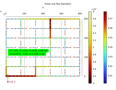
In the Text text field, type eval(dp1*exp(dp1c),kPa) kPa, eval(dp2*exp(dp2c),kPa) kPa, P=[eval(minop1(-P),kW), eval(-minop1(P),kW)] kW.
|
|
4
|
|
5
|
|
6
|
|
7
|
|
8
|
|
9
|
|
1
|
|
2
|
|
3
|
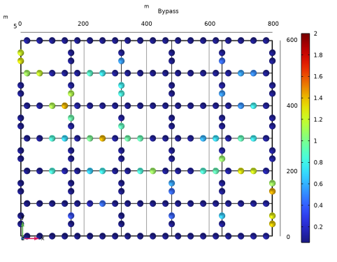
In the Text text field, type c0=[eval(minop1(exp(bypass))), eval(-minop1(-exp(bypass)))], c1=[eval(minop1(exp(consumers))), eval(-minop1(-exp(consumers)))].
|
|
4
|
|
5
|
|
6
|
|
1
|
|
2
|
|
3
|
|
1
|
|
2
|
|
3
|
|
4
|
|
5
|
|
1
|
|
2
|
|
3
|
|
1
|
|
2
|
|
3
|
|
1
|
|
2
|
|
3
|
|
1
|
In the Model Builder window, under Results, Ctrl-click to select Pressure (nipfl) 2, Velocity (nipfl) 2, Temperature (nipfl) 2, Power and Pipe Diameters, Bypass, and Consumers.
|
|
2
|
Right-click and choose Group.
|
|
1
|
|
2
|
|
3
|
Select the Plot checkbox.
|
|
4
|
|
1
|
|
2
|
|
3
|
Find the Initial values of variables solved for subsection. From the Settings list, choose User controlled.
|
|
4
|
|
5
|
|
1
|
In the Model Builder window, under Study 3: Optimization > Solver Configurations > Solution 3 (sol3) click Optimization Solver 1.
|
|
2
|
|
3
|
Select the Move limits checkbox.
|
|
4
|
|
1
|
|
2
|
|
3
|
|
4
|
|
1
|
|
2
|
|
3
|
Select the Manual color range checkbox.
|
|
4
|
|
5
|
|
6
|
|
1
|
|
2
|
|
3
|
|
1
|
|
2
|
|
3
|
|
1
|
|
2
|
|
3
|
|
4
|
Browse to the model’s Application Libraries folder and double-click the file district_heating_optimization_geom_parameters.txt.
|
|
1
|
|
2
|
|
3
|
|
4
|
Locate the Coordinates section. In the table, enter the following settings:
|
|
5
|
Locate the Selections of Resulting Entities section. Select the Resulting objects selection checkbox.
|
|
1
|
|
2
|
|
3
|
|
4
|
Select the Keep input objects checkbox.
|
|
5
|
|
1
|
|
2
|
|
3
|
Locate the Coordinates section. In the table, enter the following settings:
|
|
4
|
Locate the Selections of Resulting Entities section. Select the Resulting objects selection checkbox.
|
|
1
|
|
2
|
|
3
|
Locate the Coordinates section. In the table, enter the following settings:
|
|
1
|
|
2
|
|
3
|
|
4
|
|
5
|
|
6
|
|
7
|
|
1
|
|
2
|
|
3
|
|
4
|
|
5
|
|
6
|
|
7
|
|
1
|
|
2
|
|
3
|
|
4
|
|
5
|
|
6
|
Click OK.
|
|
1
|
|
2
|
|
3
|
|
4
|
|
5
|
|
6
|
Click OK.
|
|
1
|
|
2
|
|
3
|
|
4
|
|
5
|
|
6
|
|
7
|
|
8
|
|
9
|
Click
|
|
1
|
In the Model Builder window, under Component 1 (comp1) > Geometry 1 right-click Consumer 2 (pol3) and choose Duplicate.
|
|
2
|
|
3
|
Locate the Coordinates section. In the table, enter the following settings:
|
|
1
|
|
2
|
|
3
|
Locate the Coordinates section. In the table, enter the following settings:
|
|
1
|
|
2
|
|
3
|
Locate the Coordinates section. In the table, enter the following settings:
|
|
1
|
|
2
|
|
3
|
Locate the Coordinates section. In the table, enter the following settings:
|
|
1
|
|
2
|
|
1
|
|
2
|
|
3
|
|
4
|
|
5
|
|
6
|
|
7
|
|
8
|
|
1
|
|
2
|
|
3
|
|
1
|
|
2
|
|
3
|
|
4
|
|
1
|
|
2
|
|
3
|
|
1
|
|
2
|
|
3
|
|
4
|
|
5
|
|
6
|
Click OK.
|
|
1
|
|
2
|
|
3
|
|
4
|
|
5
|
|
1
|
|
2
|
|
3
|
|
4
|
|
5
|
Click
|
|
1
|
|
2
|
|
3
|
|
4
|
|
5
|
|
6
|
|
7
|
Click OK.
|
|
8
|
|
1
|
In the Model Builder window, under Component 1 (comp1) > Geometry 1 right-click Hot Flow (boxsel1) and choose Duplicate.
|
|
2
|
|
3
|
|
4
|
|
5
|
Click
|
|
6
|
|
7
|
Click OK.
|
|
1
|
|
2
|
|
3
|
|
4
|
|
5
|
In the Add dialog, in the Selections to add list, choose Inlet 1 Line, Outlet 1 Line, Outlet 2 Line, and Inlet 2 Line.
|
|
6
|
Click OK.
|