
|
|
|

|
1
|
|
2
|
In the Application Libraries window, select Fatigue Module > Stress Life > bracket_fatigue in the tree.
|
|
3
|
Click
|
|
1
|
|
2
|
|
1
|
|
2
|
|
3
|
|
1
|
|
2
|
|
3
|
|
1
|
|
2
|
|
3
|
|
1
|
|
2
|
In the Settings window for Global Evaluation, click Add Expression in the upper-right corner of the Expressions section. From the menu, choose Component 1 (comp1) > Solid Mechanics > Global > solid.Ws_tot - Total elastic strain energy - J.
|
|
3
|
|
1
|
|
2
|
|
1
|
|
2
|
|
3
|
|
4
|
|
5
|
Click
|
|
6
|
|
7
|
Click OK.
|
|
1
|
|
2
|
|
3
|
|
4
|
|
5
|
|
6
|
|
7
|
Click OK.
|
|
1
|
|
2
|
|
3
|
|
4
|
Locate the Output Entities section. From the Geometric entity level list, choose Adjacent boundaries.
|
|
5
|
|
6
|
|
7
|
Click OK.
|
|
1
|
|
2
|
|
3
|
|
4
|
|
5
|
Click OK.
|
|
1
|
|
2
|
|
3
|
|
4
|
Click Replace Expression in the upper-right corner of the P-Norm section. From the menu, choose Component 1 (comp1) > Solid Mechanics > Stress > comp1.solid.mises - von Mises stress - N/m².
|
|
5
|
|
6
|
|
7
|
|
1
|
|
2
|
|
3
|
|
1
|
|
2
|
|
3
|
|
1
|
|
2
|
|
3
|
|
4
|
Locate the Control Variable Settings section. In the text field, type 3[mm], which corresponds to twice the maximum displacement.
|
|
1
|
|
2
|
|
3
|
|
4
|
|
5
|
|
1
|
|
2
|
Go to the Add Study window.
|
|
3
|
|
4
|
Click the Add Study button in the window toolbar twice.
|
|
1
|
|
2
|
|
1
|
|
2
|
|
3
|
|
1
|
|
2
|
|
3
|
|
4
|
|
5
|
|
6
|
Click Add Expression in the upper-right corner of the Objective Function section. From the menu, choose Component 1 (comp1) > Definitions > comp1.pnorm1 - P-norm.
|
|
7
|
Locate the Objective Function section. In the table, enter the following settings:
|
|
8
|
Find the Objective settings subsection. From the Objective scaling list, choose Initial solution based.
|
|
9
|
Click Add Expression in the upper-right corner of the Constraints section. From the menu, choose Component 1 (comp1) > Definitions > Free Shape Domain 1 > comp1.fsd1.relVolume - Material volume divided by geometry volume - 1.
|
|
10
|
Click Add Expression in the upper-right corner of the Constraints section. From the menu, choose Component 1 (comp1) > Solid Mechanics > Global > comp1.solid.Ws_tot - Total elastic strain energy - J.
|
|
11
|
Locate the Constraints section. In the table, enter the following settings:
|
|
12
|
|
1
|
In the Model Builder window, expand the Study 3: Optimized Design > Solver Configurations > Solution 3 (sol3) > Optimization Solver 1 > Stationary Solver 1 > Segregated 1 node, then click Solid Mechanics.
|
|
2
|
|
3
|
From the Linear solver list, choose Suggested Iterative Solver (solid) to reduce the computational time further.
|
|
1
|
|
2
|
|
3
|
Select the Plot checkbox.
|
|
5
|
|
1
|
In the Model Builder window, under Study 2: Initial Fatigue, Ctrl-click to select Parametric Sweep and Step 1: Fatigue.
|
|
2
|
Right-click and choose Copy.
|
|
1
|
|
2
|
|
3
|
|
1
|
|
2
|
Find the Values of variables not solved for subsection. From the Study list, choose Study 3: Optimized Design, Stationary.
|
|
3
|
|
1
|
|
2
|
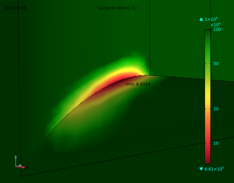
In the Settings window for 3D Plot Group, type Cycles to Failure, Optimized in the Label text field.
|
|
3
|
|
1
|
|
2
|
|
3
|
|
1
|
|
2
|
|
3
|
|
1
|
|
2
|
|
3
|
|
4
|
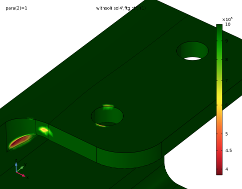
Click Add Expression in the upper-right corner of the Expressions section. From the menu, choose Component 1 (comp1) > Fatigue > ftg.ctf - Cycles to failure - 1.
|
|
1
|
|
2
|
|
3
|
|
4
|
|
1
|
|
2
|
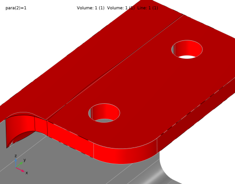
In the Settings window for 3D Plot Group, type Shape Optimization, Volumetric in the Label text field.
|
|
3
|
|
1
|
|
2
|
|
3
|
|
4
|
|
1
|
|
2
|
|
3
|
|
4
|
|
1
|
|
2
|
In the Settings window for Deformation, type Deformation 1 - Z-fighting perturbation fix in the Label text field.
|
|
3
|
|
4
|
|
5
|
|
6
|
|
1
|
|
2
|
|
3
|
|
4
|
|
5
|
|
6
|
|
1
|
|
2
|
|
1
|
|
2
|