|
|
|
|
1
|
|
2
|
|
1
|
|
2
|
|
3
|
|
4
|
|
1
|
|
2
|
|
3
|
|
4
|
|
5
|
Click to expand the Layers section. In the table, enter the following settings:
|
|
6
|
Click
|
|
7
|
|
1
|
|
2
|
|
3
|
|
4
|
Locate the Selections of Resulting Entities section. Select the Resulting objects selection checkbox.
|
|
5
|
|
6
|
Click
|
|
1
|
|
2
|
|
3
|
|
4
|
|
1
|
|
2
|
|
3
|
|
4
|
Click
|
|
1
|
|
2
|
|
3
|
|
4
|
|
5
|
|
1
|
|
2
|
|
3
|
|
4
|
|
5
|
Click OK.
|
|
6
|
|
7
|
|
8
|
|
1
|
|
2
|
|
3
|
Clear the Unite objects checkbox.
|
|
4
|
Locate the Selections of Resulting Entities section. Find the Selections from plane geometry subsection. Select the Show in physics checkbox, to make the selections from the work plane available for the physics setup.
|
|
5
|
|
1
|
|
2
|
|
3
|
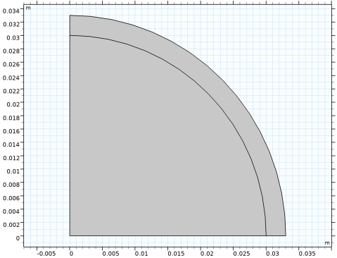
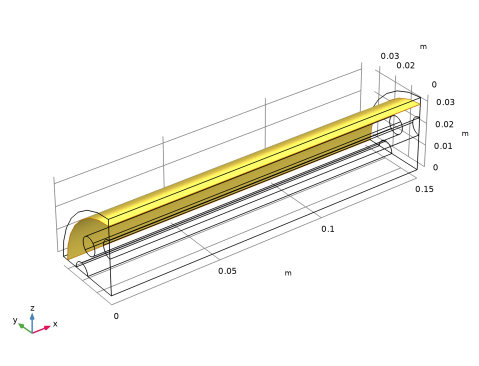
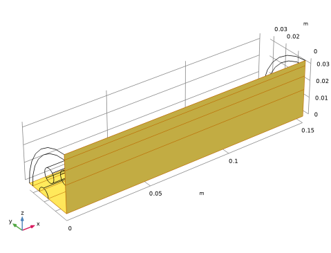
Locate the General section. From the Extrude from list, choose Faces This is the outer layer of the cross section.
|
|
4
|
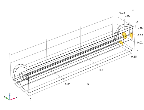
On the object wp1, select Boundary 3 only.
|
|
5
|
|
6
|
Locate the Distances section. In the table, enter the following settings:
|
|
7
|
Locate the Selections of Resulting Entities section. Select the Resulting objects selection checkbox.
|
|
8
|
|
9
|
|
1
|
|
2
|
|
3
|
|
4
|
|
5
|
|
6
|
|
7
|
Locate the Distances section. In the table, enter the following settings:
|
|
8
|
Locate the Selections of Resulting Entities section. Select the Resulting objects selection checkbox.
|
|
9
|
|
10
|
Click
|
|
11
|
|
1
|
|
2
|
|
3
|
|
4
|
|
5
|
|
6
|
|
7
|
Locate the Distances section. In the table, enter the following settings:
|
|
8
|
Locate the Selections of Resulting Entities section. Select the Resulting objects selection checkbox.
|
|
9
|
|
10
|
Click
|
|
11
|
|
1
|
|
2
|
|
3
|
Click the
|
|
1
|
|
2
|
|
3
|
|
4
|
|
5
|
|
6
|
|
1
|
|
2
|
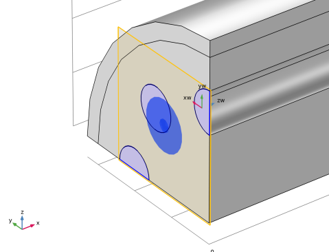
Right-click on the selected entities. From the Create Selection menu, choose Intersection Selection.
|
|
3
|
|
4
|
|
5
|
|
1
|
|
2
|
|
3
|
|
4
|
|
5
|
|
6
|
|
7
|
|
8
|
|
9
|
|
1
|
|
2
|
|
3
|
|
4
|
|
5
|
|
6
|
Go to the Selection List window.
|
|
1
|
|
2
|
|
3
|
|
4
|
|
5
|
|
6
|
Go to the Selection List window.
|
|
1
|
|
2
|
|
3
|
|
4
|
|
5
|
|
1
|
|
2
|
|
3
|
|
4
|
|
5
|
|
6
|
Click OK.
|
|
7
|
|
8
|
|
9
|
In the Add dialog, in the Selections to subtract list, choose Bed/Jacket, Tubes/Bed, Tubes Symmetry, and Bed Symmetry.
|
|
10
|
|
1
|
|
2
|
|
3
|
|
4
|
|
5
|
|
6
|
Click OK.
|
|
7
|
|
8
|
|
9
|
In the Add dialog, in the Selections to subtract list, choose Tubes Outlet (Work Plane 1) and Catalytic Bed.
|
|
10
|
|
1
|
|
2
|
|
3
|
|
4
|
|
5
|
|
6
|
Click OK.
|
|
7
|
|
8
|
|
9
|
In the Add dialog, in the Selections to subtract list, choose Bed Inlet (Work Plane 1) and Heating Tubes.
|
|
10
|
|
1
|
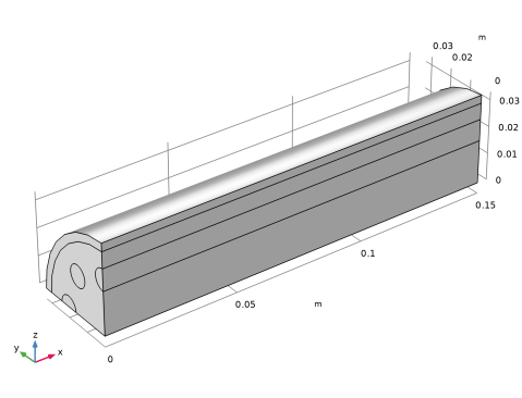
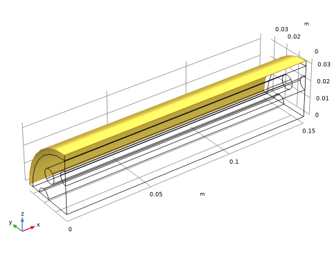
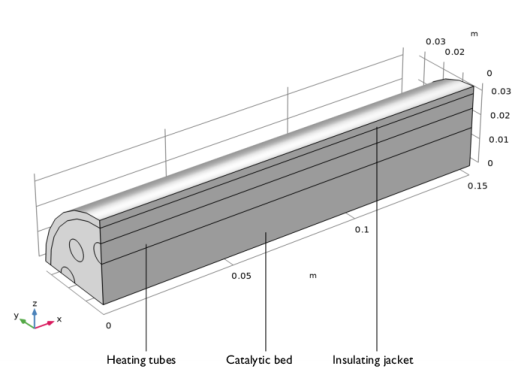
On the object fin, select Boundary 12 only. This is the outer cylindrical face.
|
|
2
|
|
3
|
|
4
|
Click
|
|
5
|