|
|
|

|
1
|
|
2
|
|
3
|
Click Add.
|
|
4
|
Click
|
|
5
|
|
6
|
Click
|
|
1
|
|
2
|
|
1
|
|
2
|
|
3
|
|
4
|
|
5
|
|
6
|
Click
|
|
1
|
|
2
|
Select the object r1 only.
|
|
3
|
|
4
|
|
5
|
Click
|
|
6
|
|
1
|
|
2
|
|
3
|
|
4
|
|
5
|
|
6
|
Click
|
|
7
|
|
1
|
|
2
|
Click in the Graphics window and then press Ctrl+A to select both objects.
|
|
3
|
|
1
|
|
2
|
Select the object int1 only.
|
|
3
|
|
4
|
|
5
|
|
6
|
Click
|
|
7
|
|
1
|
|
2
|
|
3
|
|
4
|
Click
|
|
5
|
|
1
|
|
2
|
|
3
|
|
4
|
Click
|
|
1
|
|
2
|
Click in the Graphics window and then press Ctrl+A to select all objects.
|
|
3
|
|
4
|
|
5
|
Click
|
|
1
|
|
2
|
|
3
|
|
4
|
Click
|
|
5
|
|
1
|
|
2
|
Go to the Add Material window.
|
|
3
|
|
4
|
Click the Add to Component button in the window toolbar.
|
|
5
|
|
1
|
|
2
|
|
3
|
|
4
|
|
5
|
Click OK.
|
|
6
|
|
7
|
|
8
|
Click
|
|
9
|
Locate the Material Contents section. In the table, enter the following settings:
|
|
1
|
|
3
|
|
4
|
|
5
|
Specify the e vector as
|
|
6
|
Locate the Constitutive Relation Jc-E section. From the σ list, choose User defined. Locate the Constitutive Relation D-E section. From the εr list, choose User defined.
|
|
1
|
|
3
|
|
4
|
|
5
|
Specify the e vector as
|
|
6
|
Locate the Constitutive Relation Jc-E section. From the σ list, choose User defined. Locate the Constitutive Relation D-E section. From the εr list, choose User defined.
|
|
1
|
|
3
|
|
4
|
|
5
|
Specify the e vector as
|
|
6
|
Locate the Constitutive Relation Jc-E section. From the σ list, choose User defined. Locate the Constitutive Relation D-E section. From the εr list, choose User defined.
|
|
1
|
|
3
|
|
4
|
|
5
|
Specify the e vector as
|
|
6
|
Locate the Constitutive Relation Jc-E section. From the σ list, choose User defined. Locate the Constitutive Relation D-E section. From the εr list, choose User defined.
|
|
1
|
|
1
|
|
2
|
|
3
|
|
4
|
|
1
|
|
2
|
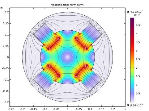
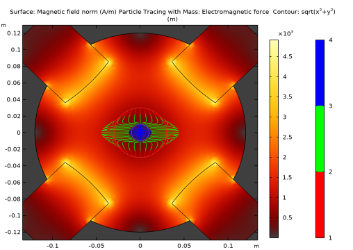
In the Settings window for Surface, click Replace Expression in the upper-right corner of the Expression section. From the menu, choose Component 1 (comp1) > Magnetic Fields > Magnetic > mf.normH - Magnetic field norm - A/m.
|
|
3
|
|
4
|
|
1
|
|
2
|
|
1
|
|
2
|
In the Settings window for Surface, click Replace Expression in the upper-right corner of the Expression section. From the menu, choose Component 1 (comp1) > Magnetic Fields > Magnetic > mf.normH - Magnetic field norm - A/m.
|
|
3
|
|
4
|
|
5
|
In the Show More Options dialog, in the tree, select the checkbox for the node Results > All Plot Types.
|
|
6
|
Click OK.
|
|
1
|
|
2
|
|
3
|
In the Fx text field, type -q*vz*mf.By*(1-2*(partt>L1/vz)+2*(partt>(L1+L2)/vz)-(partt>(L1+L2+L3)/vz)).
|
|
4
|
In the Fy text field, type q*vz*mf.Bx*(1-2*(partt>L1/vz)+2*(partt>(L1+L2)/vz)-(partt>(L1+L2+L3)/vz)).
|
|
5
|
|
6
|
|
7
|
|
1
|
|
2
|
|
3
|
|
4
|
|
5
|
|
6
|
|
1
|
|
2
|
|
3
|
Click to expand the Coloring and Style section. Click to expand the Quality section. Find the ODE solver settings subsection. In the Relative tolerance text field, type 1e-6.
|
|
4
|
|
5
|
|
6
|
Find the Instantaneous flow field subsection.
|
|
7
|
|
8
|
|
1
|
|
2
|
|
3
|
|
4
|
|
5
|
|
6
|
|
7
|
|
8
|
Clear the Color legend checkbox.
|
|
9
|