|
|
|
|
1
|
|
2
|
Click
|
|
1
|
|
2
|
|
3
|
Click
|
|
4
|
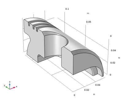
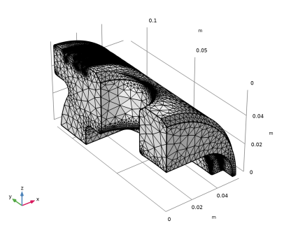
Browse to the model’s Application Libraries folder and double-click the file piston_quarter.mphbin.
|
|
5
|
Click
|
|
1
|
|
2
|
|
3
|
|
4
|
|
5
|
|
6
|
|
1
|
In the Mesh toolbar, click
|
|
2
|
|
3
|
|
4
|
|
5
|
|
6
|
Click
|
|
1
|
|
1
|
|
1
|
|
2
|
|
4
|
|
5
|
Locate the Element Size Parameters section.
|
|
6
|
|
7
|
|
1
|
|
2
|
|
3
|
|
4
|
|
5
|
|
6
|
|
7
|
|
2
|
|
3
|
|
4
|
|
5
|
Click
|
|
6
|
|
7
|
|
8
|
|
1
|
|
2
|
|
3
|
Click the Custom button.
|
|
4
|
Locate the Element Size Parameters section. In the Maximum element growth rate text field, type 1.8.
|
|
5
|
|
6
|
|
7
|
Click
|
|
1
|
|
2
|
Select the Enable filter checkbox.
|
|
3
|
|
4
|
|
5
|