|
|
|
|
1
|
|
2
|
|
3
|
Click
|
|
4
|
Browse to the model’s Application Libraries folder and double-click the file busbar_assembly_groups_geom_parameters.txt.
|
|
1
|
|
2
|
|
1
|
|
2
|
|
3
|
|
4
|
|
5
|
|
6
|
|
7
|
|
8
|
Locate the Selections of Resulting Entities section. Find the Cumulative selection subsection. Click New.
|
|
9
|
|
10
|
Click OK.
|
|
11
|
In the Settings window for Block, click
|
|
12
|
|
1
|
|
2
|
|
3
|
|
4
|
On the object blk1, select Boundary 4 only.
|
|
5
|
Click to expand the Local Coordinate System section. In the xw-displacement text field, type -c_g_w/2+s_di.
|
|
6
|
|
7
|
|
1
|
|
1
|
|
2
|
|
4
|
|
1
|
In the Model Builder window, under Component 1 (comp1) > Geometry 1 right-click Work Plane 1 (wp1) and choose Extrude.
|
|
2
|
|
4
|
Locate the Selections of Resulting Entities section. Find the Cumulative selection subsection. From the Contribute to list, choose Titanium.
|
|
5
|
|
1
|
In the Model Builder window, under Component 1 (comp1) > Geometry 1, Ctrl-click to select Work Plane 1 (wp1) and Extrude 1 (ext1).
|
|
2
|
Right-click and choose Group.
|
|
1
|
|
2
|
|
3
|
|
4
|
|
5
|
|
6
|
|
7
|
|
8
|
|
9
|
|
1
|
|
2
|
|
4
|
Click
|
|
1
|
|
2
|
|
3
|
|
4
|
|
1
|
|
2
|
|
3
|
|
4
|
|
5
|
Click
|
|
1
|
In the Model Builder window, under Component 1 (comp1) > Geometry 1 right-click Work Plane 2 (wp2) and choose Revolve.
|
|
2
|
|
3
|
|
4
|
|
5
|
|
6
|
|
7
|
Locate the Selections of Resulting Entities section. Find the Cumulative selection subsection. From the Contribute to list, choose Titanium.
|
|
8
|
Click
|
|
9
|
|
1
|
In the Model Builder window, under Component 1 (comp1) > Geometry 1, Ctrl-click to select Work Plane 2 (wp2) and Revolve 1 (rev1).
|
|
2
|
Right-click and choose Group.
|
|
1
|
|
2
|
|
3
|
|
4
|
|
5
|
|
6
|
|
7
|
|
8
|
Click
|
|
9
|
|
10
|
|
1
|
|
2
|
|
1
|
|
2
|
|
3
|
|
4
|
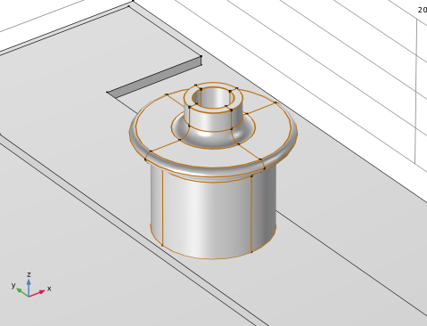
On the object cyl1, select Boundary 4 only, the top boundary of the cylinder.
|
|
5
|
|
6
|
Click
|
|
1
|
|
2
|
|
3
|
|
4
|
Select the object cyl1 only.
|
|
5
|
Click
|
|
1
|
|
2
|
|
3
|
|
4
|
|
5
|
|
6
|
Click
|
|
1
|
|
2
|
|
3
|
|
4
|
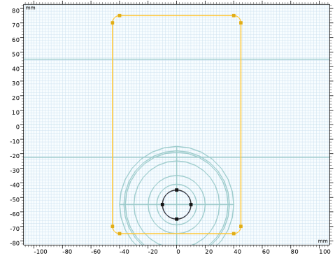
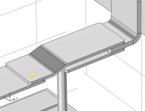
On the object r1, select Points 1–4 only.
|
|
5
|
|
1
|
|
2
|
Select the object fil1 only.
|
|
3
|
|
4
|
|
5
|
Select the object cro1 only.
|
|
6
|
|
1
|
In the Model Builder window, under Component 1 (comp1) > Geometry 1 > Rod Connector right-click Work Plane 3 (wp3) and choose Extrude.
|
|
2
|
|
4
|
Select the Reverse direction checkbox.
|
|
5
|
Click
|
|
6
|
|
7
|
|
1
|
|
2
|
|
3
|
|
4
|
|
5
|
|
6
|
|
7
|
|
8
|
|
1
|
|
2
|
|
3
|
|
4
|
Locate the Local Coordinate System section. In the xw-displacement text field, type c_g_w/4-3*b_di+r_c_w.
|
|
5
|
|
6
|
|
1
|
|
2
|
|
3
|
|
4
|
|
1
|
|
2
|
On the object r1, select Points 1 and 4 only.
|
|
3
|
|
4
|
|
5
|
Click
|
|
6
|
|
1
|
In the Model Builder window, under Component 1 (comp1) > Geometry 1 right-click Work Plane 4 (wp4) and choose Extrude.
|
|
2
|
|
4
|
Click
|
|
1
|
|
2
|
|
3
|
|
4
|
|
5
|
Locate the Local Coordinate System section. In the xw-displacement text field, type c_g_l/4-a_c_w/2.
|
|
6
|
|
7
|
|
1
|
|
2
|
|
3
|
|
4
|
|
1
|
|
2
|
On the object r1, select Points 3 and 4 only.
|
|
3
|
|
4
|
|
5
|
Click
|
|
1
|
In the Model Builder window, under Component 1 (comp1) > Geometry 1 right-click Work Plane 5 (wp5) and choose Extrude.
|
|
2
|
|
4
|
Select the Reverse direction checkbox.
|
|
5
|
Click
|
|
1
|
|
2
|
|
3
|
|
4
|
Locate the Local Coordinate System section. In the xw-displacement text field, type c_g_w/4-3*b_di+r_c_w+e_c_lx.
|
|
5
|
|
6
|
|
1
|
|
2
|
|
3
|
|
4
|
|
5
|
|
6
|
Click
|
|
1
|
Right-click Component 1 (comp1) > Geometry 1 > Work Plane 6 (wp6) > Plane Geometry > Circle 1 (c1) and choose Duplicate.
|
|
2
|
|
3
|
|
4
|
Click
|
|
1
|
|
2
|
Select the object c2 only.
|
|
3
|
|
4
|
|
5
|
Select the object c1 only.
|
|
6
|
Click
|
|
7
|
|
1
|
In the Model Builder window, under Component 1 (comp1) > Geometry 1 right-click Work Plane 6 (wp6) and choose Extrude.
|
|
2
|
|
3
|
|
4
|
|
5
|
|
6
|
Click
|
|
1
|
|
2
|
|
3
|
|
4
|
Clear the Keep interior boundaries checkbox.
|
|
5
|
|
1
|
|
2
|
|
3
|
In the Model Builder window, under Component 1 (comp1) > Geometry 1, Ctrl-click to select Work Plane 4 (wp4), Extrude 3 (ext3), Work Plane 5 (wp5), Extrude 4 (ext4), Work Plane 6 (wp6), Extrude 5 (ext5), and Union 1 (uni1).
|
|
4
|
|
5
|
|
1
|
|
2
|
|
3
|
|
4
|
Locate the Local Coordinate System section. In the xw-displacement text field, type c_g_h+s_h+c_c_h-c_c_d+r_l.
|
|
5
|
|
6
|
|
1
|
|
2
|
|
1
|
|
2
|
|
4
|
|
1
|
|
2
|
|
3
|
|
4
|
|
1
|
|
2
|
|
3
|
|
4
|
|
5
|
|
1
|
In the Model Builder window, under Component 1 (comp1) > Geometry 1 right-click Work Plane 7 (wp7) and choose Extrude.
|
|
2
|
|
4
|
Click
|
|
5
|
|
1
|
|
2
|
|
3
|
|
4
|
Locate the Local Coordinate System section. In the xw-displacement text field, type -c_g_w/4-b_di*3+r_c_w.
|
|
5
|
|
6
|
|
1
|
|
2
|
|
3
|
|
4
|
|
5
|
Click
|
|
6
|
|
1
|
|
2
|
|
3
|
On the object r1, select Points 1–4 only.
|
|
4
|
|
5
|
|
6
|
Click
|
|
1
|
In the Model Builder window, under Component 1 (comp1) > Geometry 1 right-click Work Plane 8 (wp8) and choose Extrude.
|
|
2
|
|
4
|
|
1
|
|
2
|
|
3
|
|
1
|
|
2
|
|
3
|
In the Model Builder window, under Component 1 (comp1) > Geometry 1, Ctrl-click to select Work Plane 7 (wp7), Extrude 6 (ext6), Work Plane 8 (wp8), Extrude 7 (ext7), and Intersection 1 (int1).
|
|
4
|
|
5
|
|
1
|
|
2
|
|
3
|
|
4
|
|
5
|
|
6
|
|
7
|
|
8
|
|
9
|
|
10
|
|
11
|
Right-click Component 1 (comp1) > Geometry 1 > Angle Connector > Intercell Busbar and choose Move Out.
|
|
12
|
|
13
|
Click
|
|
14
|
|
1
|
|
2
|
|
3
|
|
4
|
|
5
|
Locate the Coordinate System section. From the Work plane list, choose Work Plane 8 (wp8). We can now define the position of the cylinder relative to the origin of the selected work plane.
|
|
6
|
|
7
|
|
8
|
|
9
|
Locate the Selections of Resulting Entities section. Find the Cumulative selection subsection. From the Contribute to list, choose Titanium.
|
|
10
|
|
1
|
|
2
|
|
3
|
|
4
|
|
5
|
|
6
|
|
7
|
|
8
|
|
9
|
Locate the Selections of Resulting Entities section. Find the Cumulative selection subsection. From the Contribute to list, choose Titanium.
|
|
10
|
|
1
|
|
2
|
|
3
|
|
4
|
|
5
|
|
6
|
|
7
|
|
8
|
|
9
|
Locate the Selections of Resulting Entities section. Find the Cumulative selection subsection. From the Contribute to list, choose Titanium.
|
|
10
|
Click
|
|
1
|
|
2
|
Select the object cyl4 only.
|
|
3
|
|
4
|
Select the Keep input objects checkbox.
|
|
5
|
|
1
|
|
2
|
|
3
|
|
4
|
Select the Keep input objects checkbox.
|
|
5
|
|
6
|
|
7
|
|
8
|
|
1
|
|
2
|
|
3
|
|
4
|
|
5
|
Select the Keep input objects checkbox.
|
|
6
|
|
7
|
|
8
|
|
9
|
|
10
|
|
1
|
|
2
|
|
1
|
|
2
|
|
3
|
|
4
|
|
5
|
Click OK.
|
|
1
|
|
2
|
|
3
|
Click
|
|
4
|
|
5
|
Click OK.
|
|
6
|
|
7
|
|
1
|
|
2
|
|
3
|
|
4
|
On the object fin, select Boundary 3 only, the bottom of the Cell Grid Top.
|
|
1
|
|
2
|
|
3
|
|
4
|
Scroll down in the upper section of the Selection List window, Ctrl-click to select boundaries 556 and 601.
|
|
5
|
|
1
|
|
2
|
|
3
|
|
4
|
|
5
|
|
6
|
Click OK.
|
|
7
|
|
8
|
|
9
|
In the Add dialog, in the Selections to subtract list, choose Electrolyte Boundary and Grounded Boundaries.
|
|
10
|
Click OK.
|