|
|
|
|
1
|
|
2
|
Browse to the model’s Application Libraries folder and double-click the file busbar_assembly_geom_subsequence.mph.
|
|
3
|
If necessary expand the Geometry Parts section under the Global Definitions node in the Model Builder window.
|
|
1
|
|
2
|
|
3
|
Locate the Input Parameters section. In the table, enter the following settings:
|
|
4
|
|
1
|
|
2
|
|
1
|
|
2
|
|
3
|
|
4
|
|
5
|
|
1
|
|
2
|
|
4
|
|
1
|
|
2
|
|
3
|
|
4
|
|
5
|
|
1
|
|
2
|
|
3
|
|
4
|
|
5
|
|
1
|
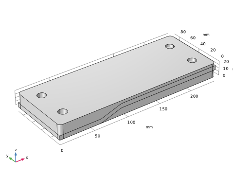
In the Model Builder window, under Global Definitions > Geometry Parts > Angle Connector right-click Work Plane 1 (wp1) and choose Extrude.
|
|
2
|
Select the first row in the Distances table.
|
|
3
|
|
4
|
|
5
|
|
6
|
|
1
|
|
2
|
|
3
|
Clear the Show work plane in instances checkbox.
|
|
1
|
|
2
|
|
1
|
|
2
|
|
3
|
|
4
|
|
5
|
|
6
|
|
7
|
Click
|
|
8
|
|
1
|
|
2
|
|
3
|
|
4
|
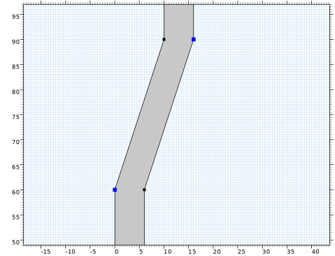
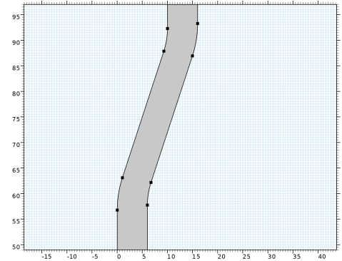
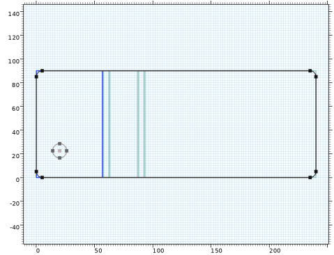
Select one vertex of r1 and drag it inward to create the fillets.
|
|
1
|
|
2
|
|
3
|
|
4
|
|
1
|
|
2
|
|
3
|
|
4
|
|
5
|
|
6
|
|
1
|
|
2
|
Select the object c1 only.
|
|
3
|
|
4
|
|
5
|
|
6
|
|
7
|
|
8
|
|
1
|
|
2
|
|
3
|
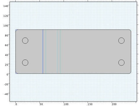
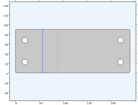
Activate the Objects to subtract section, and select the objects arr1(1,1), arr1(1,2), arr1(2,1), arr1(2,2), which are the four circles.
|
|
4
|
|
1
|
In the Model Builder window, under Global Definitions > Geometry Parts > Angle Connector right-click Work Plane 2 (wp2) and choose Extrude.
|
|
2
|
|
3
|
|
4
|
|
5
|
|
1
|
|
2
|
|
3
|
|
4
|
Select the Resulting objects selection checkbox, to make sure that this selection will be accessible from an instance of the geometry part when inserted into a geometry sequence.
|
|
5
|
|
6
|
Click the
|
|
1
|
|
2
|
|
3
|
|
4
|
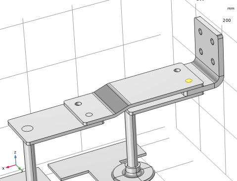
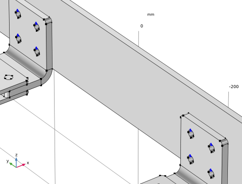
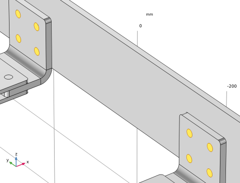
On the object int1, select Edge 74 only. This is one of the lower edges of the front right hole.
|
|
5
|
Click to expand the Local Coordinate System section. In the yw-displacement text field, type b_r_part.
|
|
1
|
|
2
|
|
3
|
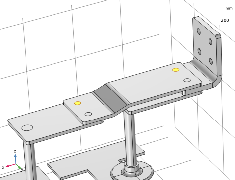
On the object int1, select Edge 26 only.
|
|
4
|
|
1
|
|
2
|
Locate the Input Parameters section. In the table, enter the following settings:
|
|
3
|
|
1
|
|
2
|
|
1
|
|
2
|
|
3
|
Click New Cumulative Selection.
|
|
4
|
|
5
|
Click OK.
|
|
6
|
|
7
|
|
1
|
|
2
|
|
4
|
Locate the Domain Selections section. In the table, enter the following settings:
|
|
5
|
Click
|
|
6
|
|
1
|
In the Model Builder window, expand the Global Definitions > Geometry Parts > Spine node, then click Central Column Position (wp2).
 |
|
1
|
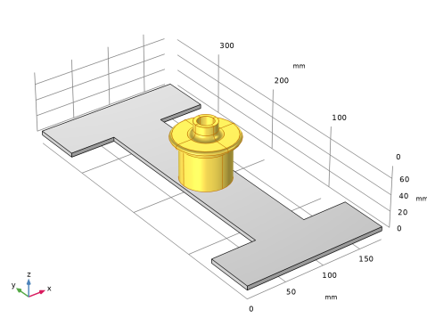
In the Model Builder window, under Global Definitions > Geometry Parts > Anode Top Assembly click Central Column 1 (pi2).
|
|
2
|
|
3
|
Find the Coordinate system to match subsection. From the Take work plane from list, choose Spine 1 (pi1).
|
|
4
|
|
5
|
|
1
|
|
2
|
|
4
|
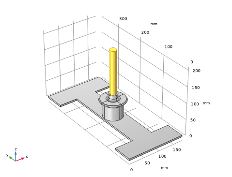
Locate the Position and Orientation of Output section. Find the Coordinate system to match subsection. From the Take work plane from list, choose Central Column 1 (pi2).
|
|
5
|
|
6
|
|
7
|
|
8
|
Click OK.
|
|
9
|
|
11
|
|
1
|
|
2
|
|
4
|
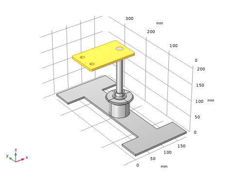
Locate the Position and Orientation of Output section. Find the Coordinate system to match subsection. From the Take work plane from list, choose Rod 1 (pi3).
|
|
5
|
|
6
|
Locate the Domain Selections section. In the table, enter the following settings:
|
|
7
|
Click
|
|
8
|
|
1
|
|
2
|
|
3
|
|
4
|
|
5
|
Click
|
|
6
|
|
1
|
|
2
|
|
4
|
Locate the Position and Orientation of Output section. Find the Coordinate system in part subsection. From the Work plane in part list, choose Rod Connector Position (wp4).
|
|
5
|
Find the Coordinate system to match subsection. From the Take work plane from list, choose Rod Connector 1 (pi4).
|
|
6
|
|
7
|
|
8
|
Locate the Domain Selections section. In the table, enter the following settings:
|
|
9
|
|
10
|
Locate the Selection Settings section. Select the Keep noncontributing selections checkbox, to make selections from this part available in instances of the Anode Top Assembly part.
|
|
11
|
In the Graphics window toolbar, click
|
|
12
|
Click
|
|
13
|
|
1
|
Go to the Selection List window.
|
|
2
|
|
4
|
|
1
|
|
2
|
|
4
|
Locate the Position and Orientation of Output section. Find the Coordinate system in part subsection. From the Work plane in part list, choose Elbow Connector Position (wp3).
|
|
5
|
Find the Coordinate system to match subsection. From the Take work plane from list, choose Elbow Connector 1 (pi5).
|
|
6
|
|
7
|
Locate the Domain Selections section. In the table, enter the following settings:
|
|
8
|
|
1
|
|
2
|
|
3
|
Locate the Position and Orientation of Output section. Find the Coordinate system to match subsection. From the Take work plane from list, choose Angle Connector 1 (pi6).
|
|
4
|
|
5
|
|
6
|
Locate the Domain Selections section. In the table, enter the following settings:
|
|
7
|
Click
|
|
1
|
|
2
|
|
3
|
Locate the Input Parameters section. In the table, enter the following settings:
|
|
4
|
Locate the Position and Orientation of Output section. Find the Coordinate system to match subsection. From the Take work plane from list, choose Elbow Connector 1 (pi5).
|
|
5
|
|
6
|
|
7
|
Locate the Domain Selections section. In the table, enter the following settings:
|
|
8
|
|
1
|
|
2
|
|
3
|
|
4
|
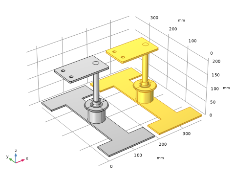
Select the Keep input objects checkbox.
|
|
5
|
Locate the Point on Plane of Reflection section. In the y text field, type 190[mm], which is half of the length of the spine.
|
|
6
|
|
7
|
|
8
|
|
9
|
|
1
|
|
2
|
|
3
|
|
4
|
|
5
|
|
6
|
|
1
|
|
2
|
|
3
|
|
4
|
|
1
|
|
2
|
|
1
|
|
2
|
|
1
|
|
2
|
|
3
|
Click New Cumulative Selection.
|
|
4
|
|
5
|
Click OK.
|
|
6
|
|
7
|
Click New Cumulative Selection again to define a selection for the copper parts.
|
|
8
|
|
9
|
Click OK.
|
|
10
|
|
12
|
Click to expand the Boundary Selections section. In the table, enter the following settings:
|
|
13
|
|
1
|
|
2
|
|
4
|
Locate the Position and Orientation of Output section. Find the Coordinate system to match subsection. From the Take work plane from list, choose Cell Grid Top 1 (pi1).
|
|
5
|
|
6
|
Click to expand the Object Selections section. In the table, enter the following settings:
|
|
7
|
Locate the Domain Selections section. In the table, enter the following settings:
|
|
8
|
Click to expand the Point Selections section. In the table, enter the following settings:
|
|
9
|
Click
|
|
10
|
In the Graphics window toolbar, click
 |
|
1
|
|
2
|
|
3
|
|
4
|
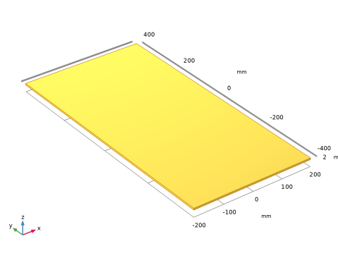
Locate the Displacement section. In the y text field, type 0 -400[mm]. By using a displacement vector, the input objects are moved to each of the positions specified by the vector.
|
|
5
|
|
1
|
|
2
|
|
4
|
Locate the Position and Orientation of Output section. Find the Coordinate system in part subsection. From the Work plane in part list, choose Elbow Connector Position (wp2).
|
|
5
|
Find the Coordinate system to match subsection. From the Take work plane from list, choose Anode Top Assembly 1 (pi2).
|
|
6
|
|
7
|
Locate the Domain Selections section. In the table, enter the following settings:
|
|
8
|
Locate the Boundary Selections section. In the table, enter the following settings:
|
|
9
|
|
1
|
|
2
|
|
3
|
Locate the Input Parameters section. In the table, enter the following settings:
|
|
4
|
Locate the Position and Orientation of Output section. Find the Rotation subsection. From the Axis type list, choose ywi-axis.
|
|
5
|
|
6
|
Locate the Domain Selections section. In the table, enter the following settings:
|
|
7
|
Click
|
|
1
|
|
2
|
Select the object pi4 only.
|
|
3
|
|
4
|
|
5
|
|
6
|
On the object pi4, select Point 1 only.
|
|
7
|
|
8
|
|
9
|
From the Vertices to move to list, choose Bolt Medium Position (Elbow Connector 1) (Anode Top Assembly 1).
|
|
10
|
|
11
|
Click
|
|
12
|
In the Graphics window toolbar, click
 |
|
13
|
|
14
|
|
15
|
|
1
|
Go to the Selection List window.
|
|
2
|
In the Domain selections tree, select Cumulative Selections > Copper and Cumulative Selections > Titanium.
|
|
3
|
|
4
|
|
1
|
|
2
|
|
3
|
|
4
|
|
5
|
|
6
|
Click OK.
|
|
7
|
|
8
|
|
9
|
In the Add dialog, in the Selections to subtract list, choose Electrolyte Boundary (Cell Grid Top 1) and Grounded Boundary (Intercell Busbar 1).
|
|
10
|
Click OK.
|
|
11
|