|
|
|
|
1
|
|
2
|
Click
|
|
1
|
|
2
|
|
3
|
Click
|
|
5
|
Click
|
|
1
|
|
2
|
|
3
|
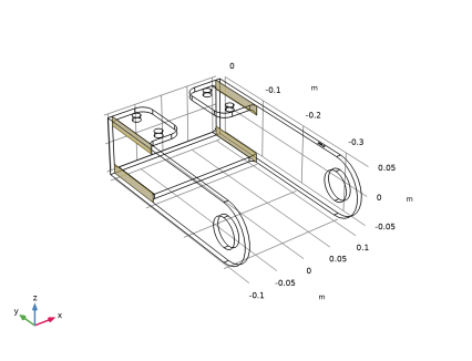
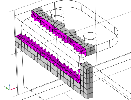
From the Elements list, choose Prisms to create a swept prism mesh. This will make it easier to see in which direction the mesh is swept.
|
|
4
|
|
5
|
|
1
|
|
2
|
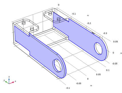
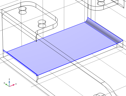
On the object imp1, select Domain 1 only.
|
|
3
|
|
4
|
|
5
|
|
6
|
|
7
|
Click
|
|
1
|
|
2
|
|
3
|
|
1
|
|
2
|
|
1
|
Go to the Cleanup Wizard window.
|
|
2
|
|
3
|
|
1
|
|
2
|
|
1
|
|
2
|
|
3
|
|
4
|
|
5
|
Click OK.
|
|
6
|
|
7
|
|
8
|
|
1
|
|
2
|
|
1
|
|
2
|
|
3
|
|
1
|
|
2
|
|
3
|
|
4
|
Click the Custom button.
|
|
5
|
|
1
|
|
2
|
|
3
|
|
4
|
Click
|
|
5
|
|
6
|
|
7
|
|
8
|
|
1
|
|
2
|
Select the Enable filter checkbox.
|
|
3
|
|
4
|
|
5
|
|
6
|
|
7
|
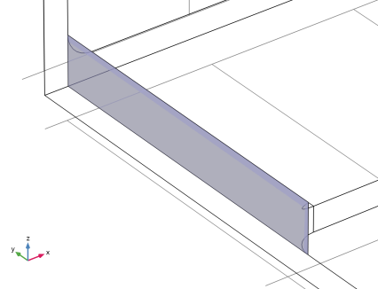
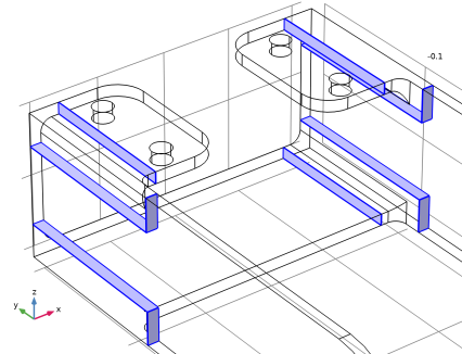
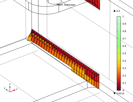
Click the Zoom Box button in the Graphics toolbar and then use the mouse to zoom in to the corner on the bracket displayed below to get a better view of the elements.
 |
|
8
|
|
1
|
|
2
|
|
1
|
|
2
|
|
3
|
|
4
|
|
5
|
|
6
|
Click
|
|
1
|
|
2
|
|
3
|
|
4
|
|
5
|
|
6
|
|
1
|
|
2
|
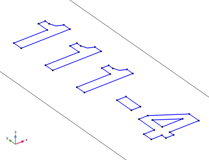
Select the object r1 only.
|
|
3
|
|
4
|
|
5
|
|
6
|
|
7
|
|
8
|
Click
|
|
9
|
|
1
|
In the Model Builder window, under Component 1 (comp1) > Geometry 1 right-click Work Plane 1 (wp1) and choose Extrude.
|
|
2
|
|
4
|
Select the Reverse direction checkbox.
|
|
5
|
Locate the Selections of Resulting Entities section. Select the Resulting objects selection checkbox.
|
|
6
|
|
7
|
Click
|
|
1
|
|
2
|
|
3
|
|
4
|
|
5
|
|
6
|
Clear the Keep objects checkbox.
|
|
7
|
Click
|
|
1
|
|
2
|
|
3
|
|
4
|
Click
|
|
1
|
Go to the Cleanup Wizard window.
|
|
2
|
Click the Refresh button in the window toolbar to make sure that the analysis is not detecting anything new in the geometry.
|
|
3
|
|
1
|
|
2
|
|
3
|
|
5
|
|
6
|
Click
|
|
1
|
|
2
|
|
3
|
|
4
|
|
1
|
|
2
|
|
3
|
|
4
|
Click the Custom button.
|
|
5
|
|
6
|
Select the Curvature factor checkbox.
|
|
1
|
|
2
|
|
3
|
|
5
|
|
6
|
Click the Custom button.
|
|
7
|
|
8
|
Select the Curvature factor checkbox.
|
|
9
|
Click
|
|
1
|
|
1
|
|
2
|
|
3
|
|
1
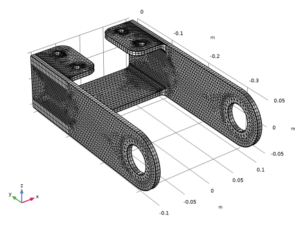
|
In the Model Builder window, under Component 1 (comp1) > Mesh 1 right-click Free Tetrahedral 1 and choose Build All.
 |
|
2
|
|
1
|
|
2
|
|
3
|
|
4
|
|
5
|
|
1
|
|
2
|
|
3
|
|
4
|
|
1
|
|
2
|
|
3
|
|
4
|
|
5
|
|
6
|
Click the Zoom Box button in the Graphics toolbar and then use the mouse to zoom in to get a better view of the elements.
 |