|
|
|
|
•
|
Structural mechanics boundary condition — constrain the bottom surface from moving axially (in the z direction), but also add an internal fluid pressure of 0.1 MPa.
|
|
•
|
|
1
|
|
2
|
In the Select Physics tree, select Structural Mechanics > Electromagnetics–Structure Interaction > Piezoelectricity > Piezoelectricity, Solid.
|
|
3
|
Click Add.
|
|
4
|
Click
|
|
5
|
|
6
|
Click
|
|
1
|
|
2
|
|
3
|
|
1
|
|
2
|
|
3
|
|
4
|
|
5
|
|
6
|
Click
|
|
1
|
|
2
|
Go to the Add Material window.
|
|
3
|
|
4
|
Click the Add to Component button in the window toolbar.
|
|
5
|
|
1
|
|
2
|
|
1
|
|
3
|
|
4
|
|
5
|
|
1
|
|
1
|
|
1
|
|
3
|
|
4
|
|
1
|
|
2
|
|
1
|
|
2
|
|
3
|
Select the Modify model configuration for study step checkbox.
|
|
4
|
|
5
|
Right-click and choose Disable.
|
|
6
|
|
1
|
In the Settings window for 2D Plot Group, type Radial Displacement (Direct Effect) in the Label text field.
|
|
1
|
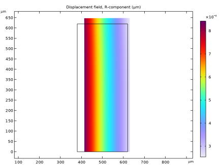
In the Model Builder window, expand the Radial Displacement (Direct Effect) node, then click Surface 1.
|
|
2
|
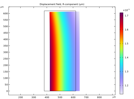
In the Settings window for Surface, click Replace Expression in the upper-right corner of the Expression section. From the menu, choose Component 1 (comp1) > Solid Mechanics > Displacement > Displacement field - m > u - Displacement field, R-component.
|
|
3
|
|
1
|
|
2
|
|
1
|
|
2
|
In the Settings window for 2D Plot Group, type Electric Potential (Direct Effect) in the Label text field.
|
|
1
|
|
2
|
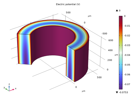
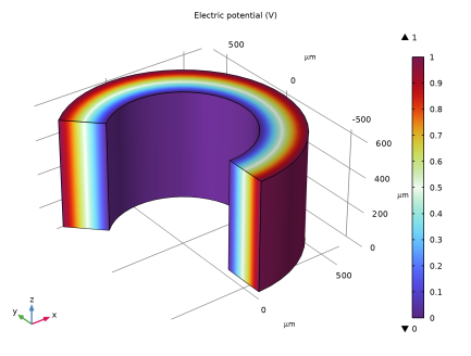
In the Settings window for 3D Plot Group, type Electric Potential, 3D (Direct Effect) in the Label text field.
|
|
3
|
|
1
|
|
2
|
|
3
|
|
4
|
|
5
|
Click
|
|
1
|
|
2
|
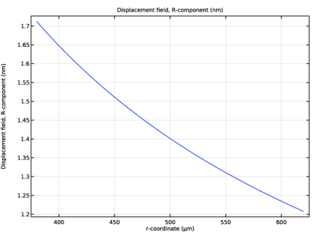
In the Settings window for 1D Plot Group, type Radial Displacement, Cut (Direct Effect) in the Label text field.
|
|
3
|
|
1
|
|
2
|
In the Settings window for Line Graph, click Replace Expression in the upper-right corner of the y-Axis Data section. From the menu, choose Component 1 (comp1) > Solid Mechanics > Displacement > Displacement field - m > u - Displacement field, R-component.
|
|
3
|
|
4
|
|
5
|
|
6
|
|
1
|
In the Model Builder window, right-click Radial Displacement, Cut (Direct Effect) and choose Duplicate.
|
|
2
|
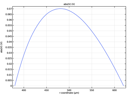
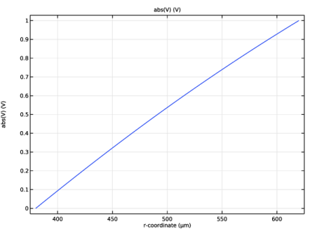
In the Settings window for 1D Plot Group, type Voltage, Cut (Direct Effect) in the Label text field.
|
|
1
|
|
2
|
|
3
|
|
4
|
|
1
|
|
2
|
Go to the Add Study window.
|
|
3
|
|
4
|
Click the Add Study button in the window toolbar.
|
|
5
|
|
1
|
|
2
|
|
3
|
Select the Modify model configuration for study step checkbox.
|
|
4
|
|
5
|
Click
|
|
6
|
|
1
|
In the Model Builder window, expand the Radial Displacement (Inverse Effect) node, then click Surface 1.
|
|
2
|
In the Settings window for Surface, click Replace Expression in the upper-right corner of the Expression section. From the menu, choose Component 1 (comp1) > Solid Mechanics > Displacement > Displacement field - m > u - Displacement field, R-component.
|
|
3
|
|
1
|
|
2
|
|
1
|
|
2
|
In the Settings window for 2D Plot Group, type Electric Potential (Inverse Effect) in the Label text field.
|
|
1
|
|
2
|
|
3
|
|
4
|
|
5
|
|
1
|
In the Model Builder window, under Results > Datasets right-click Cut Line 2D 1 and choose Duplicate.
|
|
2
|
|
3
|
|
1
|
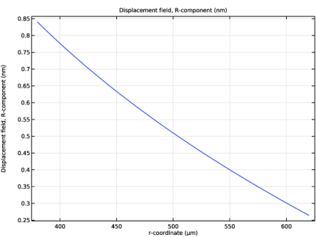
In the Model Builder window, right-click Radial Displacement, Cut (Direct Effect) and choose Duplicate.
|
|
2
|
In the Settings window for 1D Plot Group, type Radial Displacement, Cut (Inverse Effect) in the Label text field.
|
|
3
|
|
4
|
|
1
|
|
2
|
In the Settings window for 1D Plot Group, type Voltage, Cut (Inverse Effect) in the Label text field.
|
|
3
|
|
4
|