|
|
|
|
|


|
•
|
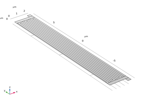
Modeling a composite laminated shell requires a 2D surface geometry, called a base surface, and a Layered Material node that adds an extra dimension (1D) to the base surface geometry in the surface normal direction. Using the Layered Material functionality, you can model several layers of different thicknesses, material properties, and fiber orientations. You can optionally specify the interface materials between the layers and the control mesh elements in each layer.
|
|
•
|
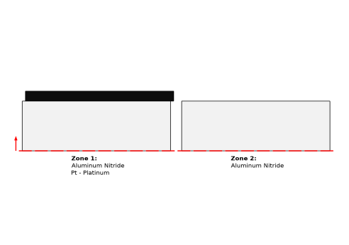
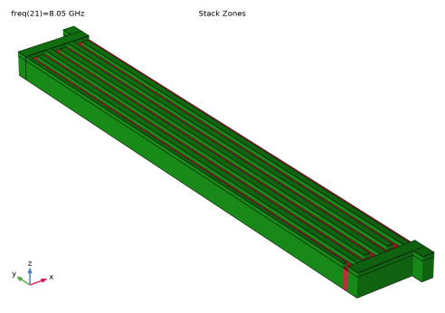
The Layered Material Stack node is used to define various zones/sections of the Lamb wave resonator.
|
|
•
|
The third direction for the selected coordinate system in the Single Layer Material, Layered Material Link, or Layered Material Stack represents the normal direction in the Layered Shell and Shell interfaces. This is also the direction in which the layer stacking is interpreted from bottom to top, and therefore, it is crucial to know it during modeling. There are two ways to achieve this:
|
|
-
|
Using physics symbols: Go to the physics settings, find the Physics Symbols section, and select the Enable physics symbols checkbox. Then go to the material feature, for instance, Linear Elastic Material, to see the normal direction represented by green arrows in the geometry.
|
|
-
|
Using result templates: When a solution dataset is available, use the result template Thickness and Orientation to plot the normal direction.
|
|
1
|
|
2
|
In the Select Physics tree, select Structural Mechanics > Electromagnetics–Structure Interaction > Piezoelectricity > Piezoelectricity, Layered Shell.
|
|
3
|
Click Add.
|
|
4
|
Click
|
|
5
|
|
6
|
Click
|
|
1
|
|
2
|
|
3
|
|
1
|
|
2
|
|
1
|
|
2
|
Go to the Add Material window.
|
|
3
|
|
4
|
Click the Add to Global Materials button in the window toolbar.
|
|
5
|
|
6
|
Click the Add to Global Materials button in the window toolbar.
|
|
7
|
|
1
|
|
2
|
|
3
|
|
4
|
Click
|
|
5
|
Locate the Material Contents section. In the table, enter the following settings:
|
|
6
|
Locate the Material Properties section. In the Material properties tree, select Basic Properties > Relative Permittivity.
|
|
7
|
Click
|
|
8
|
Locate the Material Contents section. In the table, enter the following settings:
|
|
1
|
|
2
|
In the Settings window for Layered Material, type Layered Material: Platinum in the Label text field.
|
|
3
|
Locate the Layer Definition section. In the table, enter the following settings:
|
|
1
|
|
2
|
In the Settings window for Layered Material, type Layered Material: Aluminum Nitride in the Label text field.
|
|
3
|
Locate the Layer Definition section. In the table, enter the following settings:
|
|
1
|
|
2
|
|
3
|
|
4
|
Click
|
|
5
|
Locate the Material Contents section. In the table, enter the following settings:
|
|
1
|
|
2
|
|
1
|
|
2
|
|
3
|
|
4
|
|
5
|
|
6
|
|
1
|
|
2
|
Select the object r1 only.
|
|
3
|
|
4
|
|
5
|
|
1
|
|
2
|
|
3
|
|
4
|
Select the Keep input objects checkbox.
|
|
5
|
|
6
|
|
1
|
|
2
|
|
3
|
|
4
|
|
5
|
|
1
|
|
2
|
|
3
|
|
4
|
|
5
|
|
6
|
|
1
|
|
2
|
|
3
|
|
4
|
Select the Keep input objects checkbox.
|
|
5
|
|
6
|
|
1
|
|
2
|
|
3
|
|
4
|
|
5
|
|
6
|
|
1
|
|
2
|
Select the object arr1(1,1) only.
|
|
3
|
|
4
|
|
5
|
Select the object r4 only.
|
|
6
|
Select the Keep tool objects checkbox.
|
|
1
|
|
2
|
|
3
|
|
4
|
On the object par1, select Domain 1 only.
|
|
5
|
Click
|
|
6
|
|
7
|
|
1
|
|
2
|
|
3
|
|
4
|
|
5
|
|
6
|
|
7
|
|
1
|
|
2
|
|
3
|
|
4
|
|
1
|
|
2
|
|
3
|
|
4
|
|
5
|
|
6
|
Click OK.
|
|
1
|
|
2
|
|
3
|
|
4
|
|
5
|
|
1
|
|
2
|
|
3
|
|
4
|
|
5
|
|
1
|
|
2
|
|
3
|
|
4
|
|
5
|
|
1
|
|
2
|
|
3
|
|
4
|
Click
|
|
5
|
|
6
|
Click OK.
|
|
1
|
In the Model Builder window, under Component 1 (comp1) right-click Materials and choose Layers > Layered Material Stack.
|
|
2
|
|
3
|
|
1
|
In the Model Builder window, under Component 1 (comp1) > Materials > Layered Material Stack 1 (stlmat1) click Layered Material Link 1 (stlmat1.stllmat1).
|
|
2
|
|
3
|
Locate the Link Settings section. From the Material list, choose Layered Material: Aluminum Nitride (lmat2).
|
|
1
|
In the Model Builder window, right-click Layered Material Stack 1 (stlmat1) and choose Layered Material Link.
|
|
2
|
|
3
|
|
1
|
|
2
|
In the Settings window for Layered Material Stack, click Layer Cross-Section Preview in the upper-right corner of the Layered Material Settings section. From the menu, choose Create Layer Cross-Section Plot.
|
|
1
|
|
2
|
|
1
|
|
2
|
|
3
|
|
1
|
In the Model Builder window, under Component 1 (comp1) > Layered Shell (lshell) click Piezoelectric Material 1.
|
|
2
|
|
3
|
Clear the Use all layers checkbox.
|
|
4
|
|
1
|
|
2
|
|
3
|
|
1
|
|
2
|
|
3
|
|
1
|
|
2
|
|
3
|
|
1
|
|
2
|
|
3
|
|
4
|
|
5
|
|
6
|
|
7
|
|
1
|
|
2
|
|
3
|
|
4
|
|
1
|
|
2
|
|
3
|
|
4
|
|
5
|
|
6
|
|
1
|
In the Model Builder window, under Component 1 (comp1) > Electric Currents in Layered Shells (ecis) click Piezoelectric Layer 1.
|
|
2
|
|
3
|
Clear the Use all layers checkbox.
|
|
4
|
|
1
|
|
2
|
|
3
|
|
4
|
|
5
|
|
6
|
In the Selection table, enter the following settings:
|
|
1
|
|
2
|
|
3
|
|
1
|
|
2
|
|
3
|
Click the Custom button.
|
|
4
|
Locate the Element Size Parameters section.
|
|
5
|
|
6
|
Click
|
|
1
|
|
2
|
|
3
|
|
1
|
|
2
|
|
3
|
|
4
|
|
5
|
|
1
|
|
2
|
|
3
|
|
4
|
|
5
|
|
1
|
|
2
|
|
1
|
|
2
|
|
3
|
|
4
|
Click
|
|
1
|
|
2
|
|
3
|
|
4
|
|
5
|
|
6
|
|
1
|
|
2
|
|
3
|
|
4
|
Select the Description checkbox.
|
|
5
|
|
6
|
|
7
|
|
8
|
|
9
|
|
10
|
|
11
|
|
12
|
|
1
|
|
2
|
|
3
|
|
4
|
|
5
|
|
1
|
|
2
|
|
3
|
Select the Description checkbox.
|
|
4
|
|
5
|
|
6
|
|
7
|
|
1
|
|
2
|
|
3
|
Clear the Plot dataset edges checkbox.
|
|
4
|
|
5
|
|
6
|
|
1
|
|
2
|
Go to the Add Study window.
|
|
3
|
Find the Studies subsection. In the Select Study tree, select Preset Studies for Selected Multiphysics > Frequency Domain.
|
|
4
|
Click the Add Study button in the window toolbar.
|
|
5
|
|
1
|
|
2
|
|
1
|
In the Model Builder window, under Frequency Domain - 7.95 to 8.05 GHz click Step 1: Frequency Domain.
|
|
2
|
|
3
|
|
4
|
Click
|
|
5
|
|
6
|
|
7
|
|
8
|
Click Add.
|
|
9
|
|
1
|
|
2
|
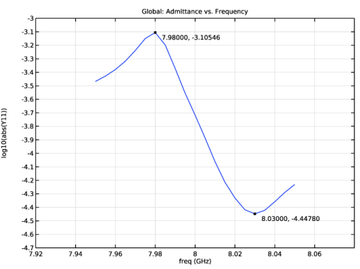
In the Settings window for 1D Plot Group, type Admittance vs. Frequency (Frequency Domain) in the Label text field.
|
|
3
|
Locate the Data section. From the Dataset list, choose Frequency Domain - 7.95 to 8.05 GHz/Solution 2 (sol2).
|
|
4
|
|
5
|
|
6
|
Locate the Plot Settings section.
|
|
7
|
|
8
|
|
9
|
|
10
|
|
11
|
|
12
|
|
13
|
|
1
|
|
2
|
|
1
|
|
2
|
|
3
|
Select the Show x-coordinate checkbox.
|
|
4
|
|
1
|
|
2
|
Go to the Result Templates window.
|
|
3
|
In the tree, select Frequency Domain - 7.95 to 8.05 GHz/Solution 2 (sol2) > Layered Shell > Geometry and Layup (lshell) > Shell Geometry (lshell).
|
|
4
|
Click the Add Result Template button in the window toolbar.
|
|
5
|
|
1
|
|
2
|
|
1
|
|
2
|
|
1
|
|
2
|
|
3
|
|
4
|
|
5
|
|
1
|
|
2
|
Drag and drop below Layer Cross-Section Preview.
|
|
3
|