
|
|
|
|
•
|
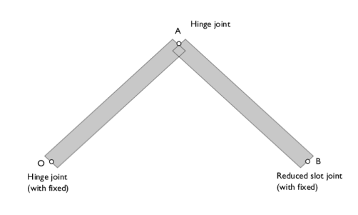
In this model, linkages are modeled as rigid elements using the Rigid Material node as we are only interested in the kinematics of the mechanism.
|
|
•
|
A Joint node can establish a connection between a Rigid Material or an Attachment node and the ground (Fixed). This helps in avoiding extra geometry components.
|
|
•
|
The given initial velocity of the slider is enforced by choosing the Force initial values option in the Consistent initialization list found in the Rigid Material node.
|
|
1
|
|
2
|
|
3
|
Click Add.
|
|
4
|
Click
|
|
5
|
|
6
|
Click
|
|
1
|
|
2
|
|
1
|
|
2
|
|
3
|
|
4
|
|
1
|
|
2
|
Select the object r1 only.
|
|
3
|
|
4
|
|
1
|
|
2
|
Select the object rot1 only.
|
|
3
|
|
4
|
Select the Keep input objects checkbox.
|
|
5
|
|
1
|
|
2
|
|
3
|
|
4
|
|
5
|
|
1
|
In the Model Builder window, under Component 1 (comp1) right-click Materials and choose Blank Material.
|
|
2
|
|
1
|
|
2
|
|
3
|
|
1
|
|
1
|
|
3
|
|
4
|
From the list, choose Locally defined.
|
|
5
|
|
6
|
Select the Translation along first axis checkbox.
|
|
1
|
|
2
|
|
3
|
Specify the du/dt vector as
|
|
5
|
|
1
|
In the Model Builder window, under Component 1 (comp1) > Multibody Dynamics (mbd) > Rigid Material 2 > Initial Values 1 click Center of Rotation: Boundary 1.
|
|
1
|
|
2
|
|
3
|
|
4
|
|
1
|
|
1
|
|
2
|
|
3
|
|
4
|
|
1
|
|
1
|
|
2
|
|
3
|
|
4
|
|
5
|
Locate the Axes of Joint section. From the Joint translational axis list, choose Attached on source.
|
|
1
|
|
1
|
In the Model Builder window, under Component 1 (comp1) > Multibody Dynamics (mbd), Ctrl-click to select Rigid Material 1 and Rigid Material 2.
|
|
2
|
Right-click and choose Group.
|
|
1
|
In the Model Builder window, under Component 1 (comp1) > Multibody Dynamics (mbd), Ctrl-click to select Hinge Joint 1, Hinge Joint 2, and Reduced Slot Joint 1.
|
|
2
|
Right-click and choose Group.
|
|
1
|
|
2
|
|
3
|
|
4
|
|
5
|
Click
|
|
1
|
|
2
|
Click in the Graphics window and then press Ctrl+A to select both domains.
|
|
1
|
|
2
|
|
1
|
|
2
|
|
3
|
|
1
|
|
2
|
|
3
|
|
4
|
|
5
|
|
1
|
|
2
|
|
3
|
|
4
|
|
1
|
|
2
|
|
3
|
|
4
|
|
1
|
|
2
|
|
3
|
|
4
|
|
5
|
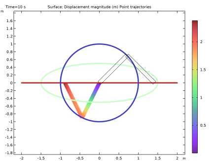
Locate the Coloring and Style section. Find the Line style subsection. From the Type list, choose Tube.
|
|
1
|
|
2
|
|
3
|
|
4
|
|
5
|
Clear the Color legend checkbox.
|
|
6
|
|
1
|
|
2
|
|
3
|
|
4
|
|
5
|
|
1
|
|
2
|
|
3
|
Click
|
|
4
|
Browse to the model’s Application Libraries folder and double-click the file slider_crank_mechanism_aA.txt.
|
|
1
|
|
2
|
|
3
|
|
4
|
|
1
|
|
2
|
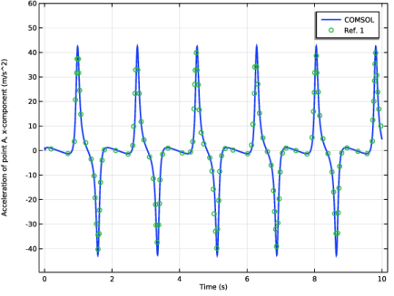
In the Settings window for Point Graph, click Replace Expression in the upper-right corner of the y-Axis Data section. From the menu, choose Component 1 (comp1) > Multibody Dynamics > Acceleration and velocity > Acceleration - m/s² > mbd.u_ttX - Acceleration, X-component.
|
|
3
|
|
4
|
|
5
|
|
1
|
|
2
|
|
3
|
|
4
|
|
5
|
|
6
|
|
8
|
|
9
|
|
1
|
|
2
|
|
3
|
Select the Manual axis limits checkbox.
|
|
4
|
|
5
|
|
6
|
Locate the Plot Settings section.
|
|
7
|
|
8
|
Select the y-axis label checkbox. In the associated text field, type Acceleration of point A, x-component (m/s^2).
|
|
9
|
|
1
|
|
2
|
|
1
|
|
2
|
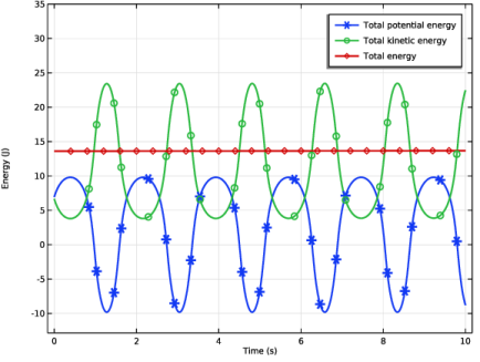
In the Settings window for Global, click Replace Expression in the upper-right corner of the y-Axis Data section. From the menu, choose Component 1 (comp1) > Definitions > Variables > Wp - Total potential energy - J.
|
|
3
|
Click Add Expression in the upper-right corner of the y-Axis Data section. From the menu, choose Component 1 (comp1) > Multibody Dynamics > Global > mbd.Wk_tot - Total kinetic energy - J.
|
|
4
|
Click Add Expression in the upper-right corner of the y-Axis Data section. From the menu, choose Component 1 (comp1) > Definitions > Variables > W - Total energy - J.
|
|
5
|
|
6
|
|
7
|
|
8
|
|
1
|
|
2
|
|
3
|
Select the Manual axis limits checkbox.
|
|
4
|
|
5
|
|
6
|
|
7
|
|
8
|
|
9
|
|
10
|
|
1
|
|
2
|
|
3
|