|
|
|
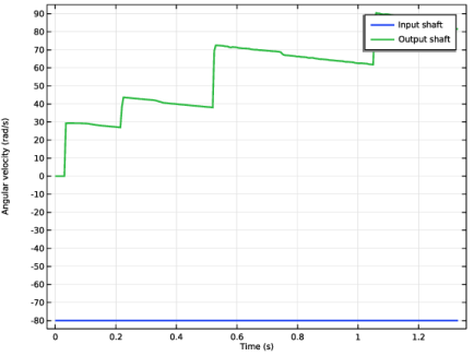
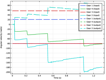
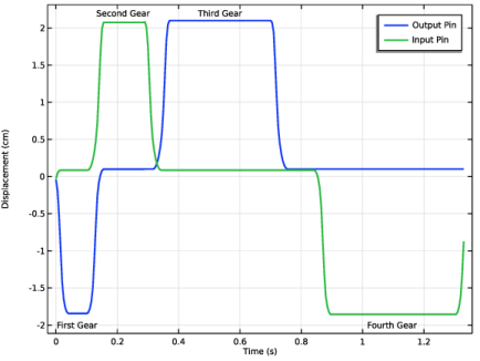
|
1
|
|
2
|
|
3
|
Click Add.
|
|
4
|
Click
 Study. Study. |
|
5
|
|
6
|
Click
 Done. Done. |
|
1
|
|
2
|
|
3
|
Click
 Load from File. Load from File. |
|
4
|
Browse to the model’s Application Libraries folder and double-click the file sequential_gearbox_with_slotted_cam_parameters.txt.
|
|
1
|
In the Model Builder window, expand the Component 1 (comp1) > Geometry 1 node, then click Geometry 1.
|
|
2
|
|
3
|
|
4
|
|
5
|
Select the Design Module Boolean operations checkbox.
|
|
1
|
|
2
|
|
3
|
Click
 Browse. Browse. |
|
4
|
Browse to the model’s Application Libraries folder and double-click the file sequential_gearbox_with_slotted_cam.mphbin.
|
|
5
|
Click
 Import. Import. |
|
1
|
|
2
|
On the object imp1(6), select Point 5 only.
|
|
3
|
|
4
|
|
5
|
On the object imp1(6), select Point 6 only.
|
|
6
|
Click
 Build Selected. Build Selected. |
|
1
|
|
2
|
|
3
|
|
4
|
In the tree, select imp1(6).
|
|
5
|
On the object imp1(12), select Point 6 only.
|
|
6
|
|
7
|
In the tree, select imp1(6).
|
|
8
|
On the object imp1(12), select Point 5 only.
|
|
9
|
Click
 Build Selected. Build Selected. |
|
1
|
|
2
|
On the object imp1(6), select Points 2, 5, 6, and 9 only.
|
|
3
|
|
1
|
|
2
|
|
3
|
|
4
|
On the object imp1(6), select Points 10, 13, 14, and 17 only.
|
|
5
|
Click
 Build Selected. Build Selected. |
|
1
|
|
2
|
|
3
|
|
4
|
On the object imp1(12), select Points 2, 5, 6, and 9 only.
|
|
5
|
Click
 Build Selected. Build Selected. |
|
1
|
|
2
|
|
3
|
|
4
|
On the object imp1(12), select Points 10, 13, 14, and 17 only.
|
|
5
|
Click
 Build Selected. Build Selected. |
|
1
|
In the Model Builder window, under Component 1 (comp1) > Geometry 1, Ctrl-click to select Distance Measurement 1 (dm1), Distance Measurement 2 (dm2), Centroid Measurement 1 (cm1), Centroid Measurement 2 (cm2), Centroid Measurement 3 (cm3), and Centroid Measurement 4 (cm4).
|
|
2
|
Right-click and choose Group.
|
|
1
|
|
2
|
|
3
|
|
4
|
Clear the Create pairs checkbox.
|
|
5
|
|
6
|
|
7
|
|
8
|
Clear the Automatic detection of small details checkbox.
|
|
1
|
In the Model Builder window, expand the Component 1 (comp1) > Materials node, then click Component 1 (comp1) > Geometry 1 > Explicit Selection 1 (sel1).
|
|
2
|
|
3
|
|
4
|
On the object fin, select Boundaries 261 and 321 only.
|
|
5
|
Click
 Build Selected. Build Selected. |
|
1
|
|
2
|
|
3
|
|
4
|
On the object fin, select Boundaries 1 and 130 only.
|
|
5
|
Click
 Build Selected. Build Selected. |
|
1
|
|
2
|
|
3
|
|
4
|
On the object fin, select Boundaries 131 and 260 only.
|
|
5
|
Click
 Build Selected. Build Selected. |
|
1
|
|
2
|
|
3
|
|
4
|
On the object fin, select Boundaries 264, 265, 271–276, 279, and 282–284 only.
|
|
5
|
Click
 Build Selected. Build Selected. |
|
1
|
|
2
|
|
3
|
On the object fin, select Boundaries 292, 293, 299–302, 305–307, and 310–312 only.
|
|
4
|
Click
 Build Selected. Build Selected. |
|
1
|
|
2
|
|
3
|
On the object fin, select Boundaries 264–269, 271–297, and 299–319 only.
|
|
4
|
Click
 Build Selected. Build Selected. |
|
1
|
|
2
|
|
3
|
On the object fin, select Boundaries 1191 and 1675 only.
|
|
1
|
|
2
|
In the Settings window for Union Selection, type Groove Boundaries and Pin Ends in the Label text field.
|
|
3
|
|
4
|
|
5
|
|
6
|
Click OK.
|
|
7
|
|
1
|
In the Model Builder window, under Component 1 (comp1) > Geometry 1 right-click Pin Ends (sel7) and choose Duplicate.
|
|
2
|
|
3
|
|
4
|
On the object fin, select Domains 6, 12, 13, 16, 22–24, and 27 only.
|
|
5
|
Click
 Build Selected. Build Selected. |
|
1
|
|
2
|
|
3
|
On the object fin, select Domains 8, 11, 18, and 21 only.
|
|
4
|
Click
 Build Selected. Build Selected. |
|
1
|
In the Model Builder window, under Component 1 (comp1) > Geometry 1 right-click Groove Boundaries and Pin Ends (unisel1) and choose Duplicate.
|
|
2
|
|
3
|
|
4
|
|
5
|
|
6
|
Click OK.
|
|
7
|
|
1
|
In the Model Builder window, under Component 1 (comp1) > Geometry 1 right-click Pins (sel9) and choose Duplicate.
|
|
2
|
|
3
|
On the object fin, select Domains 5, 6, 14, 16, 22, and 26–28 only.
|
|
4
|
Click
 Build Selected. Build Selected. |
|
1
|
|
2
|
|
3
|
On the object fin, select Domains 4 and 29 only.
|
|
4
|
Click
 Build Selected. Build Selected. |
|
1
|
|
2
|
|
3
|
On the object fin, select Domains 7–9, 12, 13, 15, 17–19, and 23–25 only.
|
|
4
|
Locate the Color section. From the Color list, choose None or — if you are running the cross-platform desktop —Custom. On the cross-platform desktop, click the Color button.
|
|
5
|
Click Define custom colors.
|
|
7
|
Click Add to custom colors.
|
|
8
|
|
9
|
Click
 Build Selected. Build Selected. |
|
1
|
|
2
|
|
3
|
On the object fin, select Domains 1 and 2 only.
|
|
4
|
|
6
|
Click Add to custom colors.
|
|
7
|
|
8
|
Click
 Build Selected. Build Selected. |
|
1
|
|
2
|
|
3
|
On the object fin, select Domain 3 only.
|
|
4
|
|
6
|
Click Add to custom colors.
|
|
7
|
|
8
|
Click
 Build Selected. Build Selected. |
|
1
|
|
2
|
|
3
|
On the object fin, select Domains 10, 11, 20, and 21 only.
|
|
4
|
|
6
|
Click Add to custom colors.
|
|
7
|
|
8
|
Click
 Build Selected. Build Selected. |
|
1
|
In the Model Builder window, under Component 1 (comp1) > Geometry 1, Ctrl-click to select Cam Ends (sel1), Input Shaft Ends (sel2), Output Shaft Ends (sel3), Groove 1 Boundaries (sel4), Groove 2 Boundaries (sel5), Groove Boundaries (sel6), Pin Ends (sel7), Groove Boundaries and Pin Ends (unisel1), Slots (sel8), Pins (sel9), Slots and Pins (unisel2), Free Rotating Gears (sel10), Fixed Gears (sel11), Sliding Gears (sel12), Shafts (sel13), Cam (sel14), and Shift Forks (sel15).
|
|
2
|
Right-click and choose Group.
|
|
1
|
|
2
|
|
3
|
|
4
|
Locate the Definition section. Find the Intervals subsection. In the table, enter the following settings:
|
|
5
|
|
6
|
|
7
|
Click to expand the Local Parameters section. In the table, enter the following settings:
|
|
1
|
|
2
|
|
3
|
|
4
|
|
1
|
|
2
|
Go to the Add Material window.
|
|
3
|
|
4
|
Right-click and choose Add to Component 1 (comp1).
|
|
5
|
|
1
|
|
3
|
|
1
|
|
2
|
|
3
|
|
1
|
|
2
|
|
3
|
|
1
|
|
2
|
|
3
|
|
1
|
|
2
|
|
3
|
|
1
|
|
2
|
|
3
|
|
1
|
|
2
|
|
3
|
|
1
|
In the Model Builder window, under Component 1 (comp1) > Multibody Dynamics (mbd), Ctrl-click to select Cam, Input Shaft, Output Shaft, Shift Fork 1, Shift Fork 2, Input Pin, and Output Pin.
|
|
2
|
Right-click and choose Group.
|
|
1
|
|
2
|
|
4
|
|
5
|
|
6
|
|
7
|
|
8
|
|
1
|
|
2
|
|
3
|
|
5
|
|
6
|
|
7
|
|
1
|
|
2
|
|
3
|
|
5
|
|
6
|
|
7
|
|
1
|
|
2
|
|
3
|
|
5
|
|
6
|
|
7
|
|
1
|
|
2
|
|
3
|
|
5
|
|
6
|
|
7
|
|
1
|
|
2
|
|
3
|
|
5
|
|
6
|
|
7
|
|
1
|
|
2
|
|
3
|
|
5
|
|
6
|
|
7
|
|
1
|
|
2
|
|
3
|
|
5
|
|
6
|
|
7
|
|
1
|
In the Model Builder window, under Component 1 (comp1) > Multibody Dynamics (mbd), Ctrl-click to select Spur Gear 1 (Input), Spur Gear 1 (Output), Spur Gear 4 (Input), Spur Gear 4 (Output), Spur Gear 3 (Input), Spur Gear 3 (Output), Spur Gear 2 (Input), and Spur Gear 2 (Output).
|
|
2
|
Right-click and choose Group.
|
|
1
|
|
2
|
|
3
|
|
4
|
|
1
|
|
2
|
|
3
|
|
4
|
|
1
|
|
2
|
|
3
|
|
4
|
|
1
|
|
2
|
|
3
|
|
4
|
|
1
|
In the Model Builder window, under Component 1 (comp1) > Multibody Dynamics (mbd), Ctrl-click to select Gear Pair: First, Gear Pair: Fourth, Gear Pair: Third, and Gear Pair: Second.
|
|
2
|
Right-click and choose Group.
|
|
1
|
|
2
|
|
3
|
|
4
|
|
1
|
|
2
|
|
3
|
|
4
|
|
1
|
|
2
|
|
3
|
|
4
|
|
1
|
|
2
|
|
3
|
|
4
|
|
1
|
|
2
|
|
3
|
|
4
|
|
1
|
|
2
|
|
3
|
|
1
|
|
2
|
|
3
|
|
4
|
|
1
|
|
2
|
|
3
|
|
1
|
|
2
|
|
3
|
|
1
|
|
2
|
|
3
|
|
1
|
In the Model Builder window, under Component 1 (comp1) > Multibody Dynamics (mbd) right-click Hinge Joint 6 and choose Duplicate.
|
|
2
|
|
3
|
|
1
|
|
2
|
|
3
|
|
1
|
|
2
|
|
3
|
Specify the M vector as
|
|
1
|
|
2
|
|
3
|
|
4
|
|
5
|
|
1
|
|
2
|
|
1
|
|
2
|
|
3
|
|
4
|
|
1
|
In the Model Builder window, under Component 1 (comp1) > Multibody Dynamics (mbd), Ctrl-click to select Hinge Joint 1, Hinge Joint 2, Hinge Joint 3, Hinge Joint 4, Hinge Joint 5, Hinge Joint 6, Hinge Joint 7, Hinge Joint 8, and Hinge Joint 9.
|
|
2
|
Right-click and choose Group.
|
|
1
|
|
2
|
|
3
|
|
4
|
|
1
|
|
2
|
|
3
|
|
4
|
|
1
|
|
2
|
|
3
|
|
4
|
|
1
|
|
2
|
|
3
|
|
4
|
|
1
|
In the Model Builder window, under Component 1 (comp1) > Multibody Dynamics (mbd), Ctrl-click to select Fixed Joint 1, Fixed Joint 2, Fixed Joint 3, and Fixed Joint 4.
|
|
2
|
Right-click and choose Group.
|
|
1
|
|
2
|
|
3
|
|
4
|
|
1
|
|
2
|
|
3
|
|
4
|
|
1
|
In the Model Builder window, under Component 1 (comp1) > Multibody Dynamics (mbd), Ctrl-click to select Prismatic Joint 1 and Prismatic Joint 2.
|
|
2
|
Right-click and choose Group.
|
|
1
|
|
2
|
|
3
|
|
4
|
|
1
|
|
2
|
|
3
|
|
1
|
In the Model Builder window, under Component 1 (comp1) > Multibody Dynamics (mbd) right-click Cylindrical Joint 1 and choose Duplicate.
|
|
2
|
|
3
|
|
4
|
|
1
|
In the Model Builder window, under Component 1 (comp1) > Multibody Dynamics (mbd), Ctrl-click to select Cylindrical Joint 1 and Cylindrical Joint 2.
|
|
2
|
Right-click and choose Group.
|
|
1
|
|
2
|
|
3
|
|
4
|
|
5
|
|
1
|
|
2
|
|
3
|
|
4
|
|
1
|
In the Model Builder window, under Component 1 (comp1) > Multibody Dynamics (mbd), Ctrl-click to select Cam–Follower 1 and Cam–Follower 2.
|
|
2
|
Right-click and choose Group.
|
|
1
|
|
2
|
|
3
|
|
4
|
|
5
|
|
6
|
|
7
|
|
8
|
|
10
|
|
1
|
|
2
|
|
3
|
|
4
|
|
1
|
|
2
|
|
3
|
|
4
|
|
5
|
|
6
|
|
1
|
|
2
|
|
3
|
|
1
|
In the Model Builder window, under Component 1 (comp1) > Multibody Dynamics (mbd), Ctrl-click to select Rigid Body Contact 1, Rigid Body Contact 2, Rigid Body Contact 3, and Rigid Body Contact 4.
|
|
2
|
Right-click and choose Group.
|
|
1
|
|
2
|
|
3
|
|
1
|
|
2
|
|
3
|
Click the Custom button.
|
|
4
|
Locate the Element Size Parameters section.
|
|
5
|
|
6
|
Click
 Build Selected. Build Selected. |
|
1
|
|
2
|
|
3
|
|
4
|
|
5
|
Locate the Element Size Parameters section.
|
|
6
|
|
7
|
Click
 Build Selected. Build Selected. |
|
1
|
|
2
|
|
3
|
|
4
|
|
1
|
|
2
|
|
3
|
|
1
|
|
2
|
|
3
|
|
1
|
|
3
|
|
4
|
|
1
|
|
1
|
|
2
|
|
3
|
|
1
|
|
2
|
|
1
|
|
2
|
|
3
|
|
1
|
|
2
|
|
3
|
In the Model Builder window, under Study 1 > Solver Configurations > Solution 1 (sol1) click Time-Dependent Solver 1.
|
|
4
|
|
5
|
|
6
|
|
1
|
|
2
|
|
3
|
|
4
|
|
1
|
|
2
|
|
3
|
Click
 Clear Selection. Clear Selection. |
|
1
|
|
2
|
|
3
|
|
4
|
|
5
|
|
1
|
|
2
|
|
3
|
|
1
|
|
2
|
|
1
|
|
2
|
|
3
|
|
1
|
|
2
|
|
3
|
|
4
|
|
5
|
|
6
|
|
1
|
|
2
|
|
1
|
|
2
|
|
3
|
|
4
|
|
5
|
Click Define custom colors.
|
|
7
|
Click Add to custom colors.
|
|
8
|
|
1
|
|
2
|
|
3
|
|
1
|
|
2
|
|
3
|
|
4
|
|
6
|
Click Add to custom colors.
|
|
7
|
|
1
|
|
2
|
|
3
|
|
1
|
|
2
|
|
3
|
|
4
|
|
6
|
Click Add to custom colors.
|
|
7
|
|
1
|
|
2
|
|
1
|
In the Model Builder window, expand the Results > Gears and Shafts > Fixed Gears 1 node, then click Fixed Gears 1.
|
|
2
|
|
3
|
|
5
|
Click Add to custom colors.
|
|
6
|
|
1
|
|
2
|
|
3
|
|
4
|
|
5
|
|
1
|
|
2
|
|
3
|
|
1
|
|
2
|
|
1
|
|
2
|
In the Settings window for Global, click Add Expression in the upper-right corner of the y-Axis Data section. From the menu, choose Component 1 (comp1) > Multibody Dynamics > Hinge joints > Hinge Joint 6 > mbd.hgj6.th_t - Relative angular velocity - rad/s.
|
|
3
|
Click Add Expression in the upper-right corner of the y-Axis Data section. From the menu, choose Component 1 (comp1) > Multibody Dynamics > Hinge joints > Hinge Joint 7 > mbd.hgj7.th_t - Relative angular velocity - rad/s.
|
|
4
|
|
1
|
|
2
|
|
3
|
|
4
|
Locate the Plot Settings section.
|
|
5
|
|
6
|
Click to expand the Style Configuration section. From the Configuration list, choose Graph Plot Style 1.
|
|
7
|
|
8
|
|
1
|
|
2
|
|
1
|
|
2
|
In the Settings window for Global, click Replace Expression in the upper-right corner of the y-Axis Data section. From the menu, choose Component 1 (comp1) > Multibody Dynamics > Spur gears > Spur Gear 1 (Input) > Rigid body angular velocity (spatial frame) - rad/s > mbd.spg1.th_tx - Rigid body angular velocity, x-component.
|
|
3
|
Click Add Expression in the upper-right corner of the y-Axis Data section. From the menu, choose Component 1 (comp1) > Multibody Dynamics > Spur gears > Spur Gear 4 (Input) > Rigid body angular velocity (spatial frame) - rad/s > mbd.spg3.th_tx - Rigid body angular velocity, x-component.
|
|
4
|
Click Add Expression in the upper-right corner of the y-Axis Data section. From the menu, choose Component 1 (comp1) > Multibody Dynamics > Spur gears > Spur Gear 3 (Input) > Rigid body angular velocity (spatial frame) - rad/s > mbd.spg5.th_tx - Rigid body angular velocity, x-component.
|
|
5
|
Click Add Expression in the upper-right corner of the y-Axis Data section. From the menu, choose Component 1 (comp1) > Multibody Dynamics > Spur gears > Spur Gear 2 (Input) > Rigid body angular velocity (spatial frame) - rad/s > mbd.spg7.th_tx - Rigid body angular velocity, x-component.
|
|
6
|
Locate the Legends section. In the table, enter the following settings:
|
|
1
|
|
2
|
|
4
|
Locate the Legends section. In the table, enter the following settings:
|
|
5
|
|
6
|
|
7
|
|
8
|
|
1
|
|
2
|
|
3
|
|
4
|
Locate the Plot Settings section.
|
|
5
|
|
6
|
|
1
|
|
3
|
|
4
|
|
5
|
|
6
|
|
1
|
|
2
|
|
3
|
|
4
|
|
5
|
|
6
|
|
7
|
|
1
|
|
2
|
|
3
|
|
4
|
|
5
|
|
1
|
|
2
|
|
3
|
|
4
|
|
1
|
|
2
|
|
3
|
|
4
|
|
5
|
|
6
|
|
7
|
|
1
|
|
2
|
|
3
|
|
1
|
|
2
|
|
3
|