PDF

Transmission Ratios in a Planetary Gear Train
Introduction
Planetary gears, also known as epicyclic gear systems, are widely used in applications requiring a compact design and high torque transmission. Their ability to provide multiple gear ratios within a small footprint makes them ideal for use in automatic transmissions, electric power tools, and aerospace systems.
A planetary gear assembly typically consists of three main elements: a central sun gear, one or more planet gears that rotate around the sun gear, and an outer ring gear with internal teeth that mesh with the planet gears. The planet gears are mounted on a rotating carrier, which allows load sharing and efficient power transmission.
This example models a helical planetary gear train comprising a sun gear, ring gear, carrier, and five planet gears. Three configurations are analyzed by fixing different components:
For each configuration, a transient multibody dynamic analysis is performed to determine the angular velocities of all gears under a specified input velocity. The resulting displacements and angular velocities are plotted, and the transmission ratios are compared for the three configurations.
Model Definition
Figure 1 shows the geometry of the planetary gear train. The system consist of a central sun gear, five evenly spaced planet gears, and an outer ring gear.
Figure 1: Geometry of the planetary gear train with a fixed ring gear. Input is applied through the sun gear shaft and output is delivered through carrier shaft.
The planet gears are mounted on a carrier plate and engage simultaneously with the central sun gear and the surrounding ring gear. As they rotate about their own axes, the planet gears also revolve around the sun gear while maintaining engagement with the ring gear. Two shafts are connected to the sun gear and the carrier plate, enabling power transmission through the system.
Planetary gear trains are widely used because they offer efficient speed reduction in a compact configuration while providing high torque transmission capability. Their versatility lies in the ability to achieve different speed reduction or speed multiplication ratios simply by varying which component is fixed, which serves as the input, and which acts as the output.
The performance of a planetary gear train is often characterized by its transmission ratio: the ratio of the angular velocity of the input component to that of the output component. This ratio depends primarily on the number of teeth on the sun and ring gears. By altering which element is held stationary, driving (input), or driven (output), different transmission ratios can be achieved.
A summary of the three configurations analyzed in this model, along with the corresponding transmission ratio, is given in Table 1.
1+nr/ns
1+ns/nr
nr/ns
Gear Properties
The properties of the different gears are given in Table 2:
dp
All the gears and shafts are modeled as rigid bodies. To reduce the computation time, the gear mesh is also assumed rigid, neglecting any flexibility in the system. All components are made of steel AISI 4340.
Time-Dependent Analysis
A time-dependent analysis is carried out for the three configurations. In each case, the input shaft is driven at a constant angular velocity of 100 rad/s, and the simulation is run for a total duration of 0.25 s.
Results and Discussion
The displacements of the system for the different configurations are shown in Figure 2, Figure 3, and Figure 4.
To gain deeper insight into the dynamic behavior of the system, the time histories of the angular velocities for the major components are shown in Figure 5, Figure 6, and Figure 7. These angular velocity plots are essential for understanding the load distribution and speed relationships between components.
Figure 2: System displacement when the ring gear is fixed.
Figure 3: System displacement when the sun gear is fixed.
Figure 4: System displacement when the carrier is fixed.
Figure 5: Angular velocities of different components versus time when the ring gear is fixed.
Figure 6: Angular velocities of different components versus time when the sun gear is fixed.
Figure 7: Angular velocities of different components versus time when the carrier is fixed.
In a planetary gear train, both the transmission ratio and the direction of rotation depend on which component is fixed. Figure 8 compares the transmission ratios for the three configurations. When either the ring gear or the sun gear is fixed, the input and output shafts rotate in the same direction, and a speed reduction is achieved: the output shaft rotates more slowly than the input shaft. In contrast, when the carrier is fixed, the output shaft rotates in the opposite direction to the input shaft.
Figure 8: Transmission ratios for different configurations.
The motion of the planet gears is inherently complex and varies depending on which element is fixed. Figure 9 illustrates the trajectories of three representative points on the first planet gear for the configuration with a fixed ring gear. The center point follows a circular trajectory around the sun gear, while the surface points trace more intricate paths due to the superposition of rotation about their own axes and revolution around the sun gear.
When the sun gear is fixed, the planet gears rotate around their own axes while orbiting around the stationary sun gear. As shown in Figure 10, the path traced by a surface point on a planet gear is an epicycloid, a curve traced by a point on the circumference of a circle rolling around the outside of another fixed circle. This characteristic motion is the reason planetary gear trains are also referred to as epicyclic gear trains.
Figure 9: Trajectories of three sample points on the first planet gear when the ring gear is fixed.
Figure 10: Epicycloid traced by the planet gear when the sun gear is fixed.
Application Library path: Multibody_Dynamics_Module/Automotive_and_Aerospace/planetary_gear_train
Modeling Instructions
From the File menu, choose New.
New
In the New window, click  Model Wizard.
Model Wizard
1
In the Model Wizard window, click  3D.
2
In the Select Physics tree, select Structural Mechanics > Multibody Dynamics (mbd).
3
Click Add.
4
Click  Study.
5
In the Select Study tree, select General Studies > Time Dependent.
6
Global Definitions
Parameters 1
1
In the Model Builder window, under Global Definitions click Parameters 1.
2
In the Settings window for Parameters, locate the Parameters section.
3
Click  Load from File.
4
Geometry 1
1
In the Model Builder window, expand the Component 1 (comp1) > Geometry 1 node, then click Geometry 1.
2
In the Settings window for Geometry, locate the Advanced section.
3
From the Geometry representation list, choose CAD kernel.
Import 1 (imp1)
You can import the geometry of the gear train by browsing to the model’s Application Libraries folder.
1
In the Geometry toolbar, click  Import.
2
In the Settings window for Import, locate the Source section.
3
Click  Browse.
4
5
Click  Import.
Form Union (fin)
1
In the Model Builder window, under Component 1 (comp1) > Geometry 1 click Form Union (fin).
2
In the Settings window for Form Union/Assembly, locate the Form Union/Assembly section.
3
From the Action list, choose Form an assembly.
4
In the Geometry toolbar, click  Build All.
Definitions
Rearrange Identity Boundary Pair nodes to help automatic generation of hinge joints.
Identity Boundary Pair 5 (ap5)
1
In the Model Builder window, expand the Component 1 (comp1) > Definitions node, then click Identity Boundary Pair 5 (ap5).
2
In the Settings window for Pair, click the  Swap Source and Destination button.
3
Drag and drop above Identity Boundary Pair 1 (ap1).
Identity Boundary Pair 4 (ap4)
1
In the Model Builder window, click Identity Boundary Pair 4 (ap4).
2
In the Settings window for Pair, click the  Swap Source and Destination button.
3
Drag and drop below Identity Boundary Pair 5 (ap5).
Identity Boundary Pair 2 (ap2)
1
In the Model Builder window, click Identity Boundary Pair 2 (ap2).
2
In the Settings window for Pair, click the  Swap Source and Destination button.
3
Drag and drop below Identity Boundary Pair 4 (ap4).
Identity Boundary Pair 3 (ap3)
1
In the Model Builder window, click Identity Boundary Pair 3 (ap3).
2
In the Settings window for Pair, click the  Swap Source and Destination button.
Identity Boundary Pair 1 (ap1)
1
In the Model Builder window, click Identity Boundary Pair 1 (ap1).
2
In the Settings window for Pair, click the  Swap Source and Destination button.
Step 1 (step1)
Define a Step function to use in the expression of the input angular velocity.
1
In the Definitions toolbar, click  More Functions and choose Step.
2
In the Settings window for Step, locate the Parameters section.
3
In the Location text field, type 7.5e-3[s].
4
Click to expand the Smoothing section. In the Size of transition zone text field, type 1.5e-2.
Geometry 1
Explicit Selection 1 (sel1)
Now create selections of the geometry. You will use them later when setting up the physics and mesh.
In the Geometry toolbar, click  Selections and choose Explicit Selection.
Geometry 1
1
In the Model Builder window, expand the Component 1 (comp1) > Materials node, then click Component 1 (comp1) > Geometry 1 > Explicit Selection 1 (sel1).
2
In the Settings window for Explicit Selection, type Ring Gear in the Label text field.
3
Locate the Color section. From the Color list, choose None or — if you are running the cross-platform desktop —Custom. On the cross-platform desktop, click the Color button.
4
Click Define custom colors.
5
6
Click Add to custom colors.
7
Click Show color palette only or OK on the cross-platform desktop.
8
On the object fin, select Domains 1 and 2 only.
9
Click  Build Selected.
Sun Gear
1
Right-click Ring Gear and choose Duplicate.
2
In the Settings window for Explicit Selection, type Sun Gear in the Label text field.
3
Locate the Entities to Select section. Click the  Clear Selection button for Entities to select.
4
Locate the Color section. Click Define custom colors.
5
6
Click Add to custom colors.
7
Click Show color palette only or OK on the cross-platform desktop.
8
On the object fin, select Domain 6 only.
9
Click  Build Selected.
Planet Gears
1
Right-click Sun Gear and choose Duplicate.
2
In the Settings window for Explicit Selection, type Planet Gears in the Label text field.
3
Locate the Entities to Select section. Click the  Clear Selection button for Entities to select.
4
Locate the Color section. Click Define custom colors.
5
6
Click Add to custom colors.
7
Click Show color palette only or OK on the cross-platform desktop.
8
On the object fin, select Domains 4, 5, and 7–9 only.
9
Click  Build Selected.
Carrier
1
Right-click Planet Gears and choose Duplicate.
2
In the Settings window for Explicit Selection, type Carrier in the Label text field.
3
Locate the Entities to Select section. Click the  Clear Selection button for Entities to select.
4
Locate the Color section. Click Define custom colors.
5
6
Click Add to custom colors.
7
Click Show color palette only or OK on the cross-platform desktop.
8
On the object fin, select Domain 3 only.
9
Click  Build Selected.
Carrier (sel4), Planet Gears (sel3), Ring Gear (sel1), Sun Gear (sel2)
1
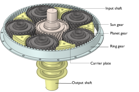
In the Model Builder window, under Component 1 (comp1) > Geometry 1, Ctrl-click to select Ring Gear (sel1), Sun Gear (sel2), Planet Gears (sel3), and Carrier (sel4).
2
Selections
In the Settings window for Group, type Selections in the Label text field.
Materials
Assign material properties. Use Steel AISI 4340 from the built-in material library.
Add Material
1
In the Materials toolbar, click  Add Material to open the Add Material window.
2
Go to the Add Material window.
3
In the tree, select Built-in > Steel AISI 4340.
4
Right-click and choose Link in Component 1 (comp1).
5
In the Materials toolbar, click  Add Material to close the Add Material window.
Multibody Dynamics (mbd)
Rigid Material: Carrier
1
In the Physics toolbar, click  Domains and choose Rigid Material.
2
3
In the Settings window for Rigid Material, type Rigid Material: Carrier in the Label text field.
Fixed Constraint 1
In the Physics toolbar, click  Attributes and choose Fixed Constraint.
Helical Gear: Ring Gear
Add Helical Gear nodes and specify the gear properties.
1
In the Physics toolbar, click  Domains and choose Helical Gear.
2
In the Settings window for Helical Gear, type Helical Gear: Ring Gear in the Label text field.
3
Locate the Domain Selection section. From the Selection list, choose Ring Gear.
4
Locate the Gear Properties section. From the Gear mesh list, choose Internal.
5
In the n text field, type nr.
6
In the dp text field, type dpr.
7
In the α text field, type alpha.
8
In the β text field, type -beta.
9
Locate the Center of Rotation section. From the list, choose User defined.
Helical Gear: Sun Gear
1
Right-click Helical Gear: Ring Gear and choose Duplicate.
2
In the Settings window for Helical Gear, type Helical Gear: Sun Gear in the Label text field.
3
Locate the Domain Selection section. Click  Clear Selection.
4
From the Selection list, choose Sun Gear.
5
Locate the Gear Properties section. From the Gear mesh list, choose External.
6
In the n text field, type ns.
7
In the dp text field, type dps.
8
In the β text field, type beta.
Helical Gear: Planet Gear 1
1
Right-click Helical Gear: Sun Gear and choose Duplicate.
2
In the Settings window for Helical Gear, type Helical Gear: Planet Gear 1 in the Label text field.
3
Locate the Domain Selection section. Click  Clear Selection.
4
5
Locate the Gear Properties section. In the n text field, type np.
6
In the dp text field, type dpp.
7
In the β text field, type -beta.
8
Locate the Center of Rotation section. Specify the Xc vector as
Helical Gear: Planet Gear 2
1
Right-click Helical Gear: Planet Gear 1 and choose Duplicate.
2
In the Settings window for Helical Gear, type Helical Gear: Planet Gear 2 in the Label text field.
3
Locate the Domain Selection section. Click  Clear Selection.
4
5
Locate the Center of Rotation section. Specify the Xc vector as
Helical Gear: Planet Gear 3
1
Right-click Helical Gear: Planet Gear 2 and choose Duplicate.
2
In the Settings window for Helical Gear, type Helical Gear: Planet Gear 3 in the Label text field.
3
Locate the Domain Selection section. Click  Clear Selection.
4
5
Locate the Center of Rotation section. Specify the Xc vector as
Helical Gear: Planet Gear 4
1
Right-click Helical Gear: Planet Gear 3 and choose Duplicate.
2
In the Settings window for Helical Gear, type Helical Gear: Planet Gear 4 in the Label text field.
3
Locate the Domain Selection section. Click  Clear Selection.
4
5
Locate the Center of Rotation section. Specify the Xc vector as
Helical Gear: Planet Gear 5
1
Right-click Helical Gear: Planet Gear 4 and choose Duplicate.
2
In the Settings window for Helical Gear, type Helical Gear: Planet Gear 5 in the Label text field.
3
Locate the Domain Selection section. Click  Clear Selection.
4
5
Locate the Center of Rotation section. Specify the Xc vector as
Helical Gear: Ring Gear
In the Model Builder window, click Helical Gear: Ring Gear.
Fixed Constraint 1
In the Physics toolbar, click  Attributes and choose Fixed Constraint.
Helical Gear: Sun Gear
In the Model Builder window, under Component 1 (comp1) > Multibody Dynamics (mbd) click Helical Gear: Sun Gear.
Fixed Constraint 1
In the Physics toolbar, click  Attributes and choose Fixed Constraint.
Select all gear features, and right click on Group to create a group.
Gears
1
In the Model Builder window, under Component 1 (comp1) > Multibody Dynamics (mbd) click Group 1.
2
In the Settings window for Group, type Gears in the Label text field.
Gear Pair: Ring-Planet 1
Use Gear Pair nodes, with different properties to connect the gears.
1
In the Physics toolbar, click  Global and choose Gear Pair.
2
In the Settings window for Gear Pair, type Gear Pair: Ring-Planet 1 in the Label text field.
3
Locate the Gear Selection section. From the Wheel list, choose Helical Gear: Ring Gear.
4
From the Pinion list, choose Helical Gear: Planet Gear 1.
Gear Pair: Ring-Planet 2
1
Right-click Gear Pair: Ring-Planet 1 and choose Duplicate.
2
In the Settings window for Gear Pair, type Gear Pair: Ring-Planet 2 in the Label text field.
3
Locate the Gear Selection section. From the Pinion list, choose Helical Gear: Planet Gear 2.
Gear Pair: Ring-Planet 3
1
Right-click Gear Pair: Ring-Planet 2 and choose Duplicate.
2
In the Settings window for Gear Pair, type Gear Pair: Ring-Planet 3 in the Label text field.
3
Locate the Gear Selection section. From the Pinion list, choose Helical Gear: Planet Gear 3.
Gear Pair: Ring-Planet 4
1
Right-click Gear Pair: Ring-Planet 3 and choose Duplicate.
2
In the Settings window for Gear Pair, type Gear Pair: Ring-Planet 4 in the Label text field.
3
Locate the Gear Selection section. From the Pinion list, choose Helical Gear: Planet Gear 4.
Gear Pair: Ring-Planet 5
1
Right-click Gear Pair: Ring-Planet 4 and choose Duplicate.
2
In the Settings window for Gear Pair, type Gear Pair: Ring-Planet 5 in the Label text field.
3
Locate the Gear Selection section. From the Pinion list, choose Helical Gear: Planet Gear 5.
Gear Pair: Sun-Planet 1
1
Right-click Gear Pair: Ring-Planet 5 and choose Duplicate.
2
In the Settings window for Gear Pair, type Gear Pair: Sun-Planet 1 in the Label text field.
3
Locate the Gear Selection section. From the Wheel list, choose Helical Gear: Sun Gear.
4
From the Pinion list, choose Helical Gear: Planet Gear 1.
Gear Pair: Sun-Planet 2
1
Right-click Gear Pair: Sun-Planet 1 and choose Duplicate.
2
In the Settings window for Gear Pair, type Gear Pair: Sun-Planet 2 in the Label text field.
3
Locate the Gear Selection section. From the Pinion list, choose Helical Gear: Planet Gear 2.
Gear Pair: Sun-Planet 3
1
Right-click Gear Pair: Sun-Planet 2 and choose Duplicate.
2
In the Settings window for Gear Pair, type Gear Pair: Sun-Planet 3 in the Label text field.
3
Locate the Gear Selection section. From the Pinion list, choose Helical Gear: Planet Gear 3.
Gear Pair: Sun-Planet 4
1
Right-click Gear Pair: Sun-Planet 3 and choose Duplicate.
2
In the Settings window for Gear Pair, type Gear Pair: Sun-Planet 4 in the Label text field.
3
Locate the Gear Selection section. From the Pinion list, choose Helical Gear: Planet Gear 4.
Gear Pair: Sun-Planet 5
1
Right-click Gear Pair: Sun-Planet 4 and choose Duplicate.
2
In the Settings window for Gear Pair, type Gear Pair: Sun-Planet 5 in the Label text field.
3
Locate the Gear Selection section. From the Pinion list, choose Helical Gear: Planet Gear 5.
Select all gear pair features, and right click on Group to create a group.
Gear Pairs
1
In the Model Builder window, under Component 1 (comp1) > Multibody Dynamics (mbd) click Group 2.
2
In the Settings window for Group, type Gear Pairs in the Label text field.
Do as follows to generate Hinge Joint nodes between components.
3
In the Model Builder window, click Multibody Dynamics (mbd).
4
In the Settings window for Multibody Dynamics, click Physics Node Generation in the upper-right corner of the Automated Model Setup section. From the menu, choose Create Joints.
Hinge Joint: Carrier-Planet 1
1
In the Model Builder window, expand the Hinge Joints node, then click Hinge Joint 1.
2
In the Settings window for Hinge Joint, type Hinge Joint: Carrier-Planet 1 in the Label text field.
Hinge Joint: Carrier-Planet 2
1
In the Model Builder window, under Component 1 (comp1) > Multibody Dynamics (mbd) > Hinge Joints click Hinge Joint 2.
2
In the Settings window for Hinge Joint, type Hinge Joint: Carrier-Planet 2 in the Label text field.
Hinge Joint: Carrier-Planet 3
1
In the Model Builder window, under Component 1 (comp1) > Multibody Dynamics (mbd) > Hinge Joints click Hinge Joint 3.
2
In the Settings window for Hinge Joint, type Hinge Joint: Carrier-Planet 3 in the Label text field.
Hinge Joint: Carrier-Planet 4
1
In the Model Builder window, under Component 1 (comp1) > Multibody Dynamics (mbd) > Hinge Joints click Hinge Joint 4.
2
In the Settings window for Hinge Joint, type Hinge Joint: Carrier-Planet 4 in the Label text field.
Hinge Joint: Carrier-Planet 5
1
In the Model Builder window, under Component 1 (comp1) > Multibody Dynamics (mbd) > Hinge Joints click Hinge Joint 5.
2
In the Settings window for Hinge Joint, type Hinge Joint: Carrier-Planet 5 in the Label text field.
Hinge Joint: Carrier
1
Right-click Hinge Joint: Carrier-Planet 5 and choose Duplicate.
2
In the Settings window for Hinge Joint, type Hinge Joint: Carrier in the Label text field.
3
Locate the Attachment Selection section. From the Source list, choose Fixed.
4
From the Destination list, choose Rigid Material: Carrier.
5
Locate the Center of Joint section. Specify the Xc vector as
Hinge Joint: Sun Gear
1
Right-click Hinge Joint: Carrier and choose Duplicate.
2
In the Settings window for Hinge Joint, type Hinge Joint: Sun Gear in the Label text field.
3
Locate the Attachment Selection section. From the Destination list, choose Helical Gear: Sun Gear.
Prescribed Motion 1
Prescribe the motion of the gear.
1
In the Physics toolbar, click  Attributes and choose Prescribed Motion.
2
In the Settings window for Prescribed Motion, locate the Prescribed Rotational Motion section.
3
From the Prescribed motion through list, choose Angular velocity.
4
In the ωp text field, type omega*step1(t).
Hinge Joint: Ring Gear
1
In the Model Builder window, right-click Hinge Joint: Sun Gear and choose Duplicate.
2
In the Settings window for Hinge Joint, type Hinge Joint: Ring Gear in the Label text field.
3
Locate the Attachment Selection section. From the Destination list, choose Helical Gear: Ring Gear.
Study 1: Fixed Ring Gear
1
In the Model Builder window, click Study 1.
2
In the Settings window for Study, type Study 1: Fixed Ring Gear in the Label text field.
Step 1: Time Dependent
1
In the Model Builder window, under Study 1: Fixed Ring Gear click Step 1: Time Dependent.
2
In the Settings window for Time Dependent, locate the Study Settings section.
3
In the Output times text field, type range(0,dt,tf).
4
Locate the Physics and Variables Selection section. Select the Modify model configuration for study step checkbox.
5
In the tree, select Component 1 (comp1) > Multibody Dynamics (mbd), Controls spatial frame > Rigid Material: Carrier > Fixed Constraint 1, Component 1 (comp1) > Multibody Dynamics (mbd), Controls spatial frame > Gears > Helical Gear: Sun Gear > Fixed Constraint 1, and Component 1 (comp1) > Multibody Dynamics (mbd), Controls spatial frame > Hinge Joints > Hinge Joint: Ring Gear.
6
Solution 1 (sol1)
1
In the Study toolbar, click  Show Default Solver.
2
In the Model Builder window, expand the Solution 1 (sol1) node.
3
In the Model Builder window, under Study 1: Fixed Ring Gear > Solver Configurations > Solution 1 (sol1) click Time-Dependent Solver 1.
4
In the Settings window for Time-Dependent Solver, click to expand the Time Stepping section.
5
From the Steps taken by solver list, choose Intermediate.
6
In the Study toolbar, click  Compute.
Add another Time Dependent study and compute the solution for the configuration with fixed sun gear.
Add Study
1
In the Home toolbar, click  Add Study to open the Add Study window.
2
Go to the Add Study window.
3
Find the Studies subsection. In the Select Study tree, select Empty Study.
4
Click the Add Study button in the window toolbar.
5
In the Home toolbar, click  Add Study to close the Add Study window.
Study 1: Fixed Ring Gear
Step 1: Time Dependent
In the Model Builder window, under Study 1: Fixed Ring Gear right-click Step 1: Time Dependent and choose Copy.
Study 2: Fixed Sun Gear
1
In the Model Builder window, right-click Study 2 and choose Paste Time Dependent.
2
In the Settings window for Study, type Study 2: Fixed Sun Gear in the Label text field.
1
In the Model Builder window, under Study 2: Fixed Sun Gear click Step 1: Time Dependent.
2
In the Settings window for Time Dependent, locate the Physics and Variables Selection section.
3
In the tree, select Component 1 (comp1) > Multibody Dynamics (mbd), Controls spatial frame > Gears > Helical Gear: Sun Gear > Fixed Constraint 1 and Component 1 (comp1) > Multibody Dynamics (mbd), Controls spatial frame > Hinge Joints > Hinge Joint: Ring Gear.
4
5
In the tree, select Component 1 (comp1) > Multibody Dynamics (mbd), Controls spatial frame > Gears > Helical Gear: Ring Gear > Fixed Constraint 1 and Component 1 (comp1) > Multibody Dynamics (mbd), Controls spatial frame > Hinge Joints > Hinge Joint: Sun Gear.
6
7
In the Model Builder window, click Study 2: Fixed Sun Gear.
8
In the Settings window for Study, locate the Study Settings section.
9
Clear the Generate default plots checkbox.
10
In the Study toolbar, click  Compute.
Add another Time Dependent study and compute the solution for the case with fixed carrier.
Add Study
1
In the Home toolbar, click  Add Study to open the Add Study window.
2
Go to the Add Study window.
3
Find the Studies subsection. In the Select Study tree, select Empty Study.
4
Click the Add Study button in the window toolbar.
5
In the Home toolbar, click  Add Study to close the Add Study window.
Study 1: Fixed Ring Gear
In the Model Builder window, under Study 1: Fixed Ring Gear right-click Step 1: Time Dependent and choose Copy.
Study 3: Fixed Carrier
1
In the Model Builder window, right-click Study 3 and choose Paste Time Dependent.
2
In the Settings window for Study, type Study 3: Fixed Carrier in the Label text field.
1
In the Model Builder window, under Study 3: Fixed Carrier click Step 1: Time Dependent.
2
In the Settings window for Time Dependent, locate the Physics and Variables Selection section.
3
In the tree, select Component 1 (comp1) > Multibody Dynamics (mbd), Controls spatial frame > Rigid Material: Carrier > Fixed Constraint 1 and Component 1 (comp1) > Multibody Dynamics (mbd), Controls spatial frame > Hinge Joints > Hinge Joint: Ring Gear.
4
5
In the tree, select Component 1 (comp1) > Multibody Dynamics (mbd), Controls spatial frame > Gears > Helical Gear: Ring Gear > Fixed Constraint 1, Component 1 (comp1) > Multibody Dynamics (mbd), Controls spatial frame > Hinge Joints > Hinge Joint: Carrier, and Component 1 (comp1) > Multibody Dynamics (mbd), Controls spatial frame > Hinge Joints > Hinge Joint: Ring Gear > Prescribed Motion 1.
6
Click  Disable.
7
In the Model Builder window, click Study 3: Fixed Carrier.
8
In the Settings window for Study, locate the Study Settings section.
9
Clear the Generate default plots checkbox.
10
In the Study toolbar, click  Compute.
Results
Follow the instructions below to plot the system displacement for different cases as shown in Figure 2, Figure 3, and Figure 4.
Displacement: Fixed Ring Gear
1
In the Model Builder window, under Results click Displacement (mbd).
2
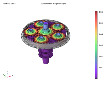
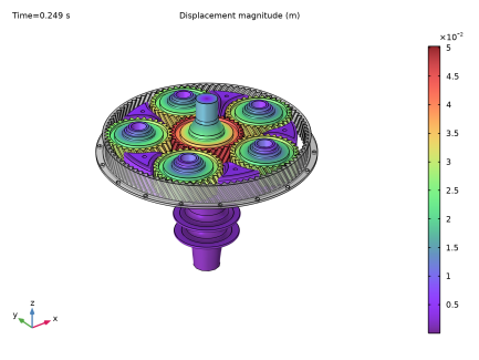
In the Settings window for 3D Plot Group, type Displacement: Fixed Ring Gear in the Label text field.
Selection 1
1
In the Model Builder window, expand the Displacement: Fixed Ring Gear node.
2
Right-click Surface and choose Selection.
3
In the Settings window for Selection, locate the Selection section.
4
From the Geometric entity level list, choose Domain.
5
Surface 2
Right-click Surface and choose Duplicate.
Selection 1
1
In the Model Builder window, expand the Surface 2 node, then click Selection 1.
2
In the Settings window for Selection, locate the Selection section.
3
Click to select the  Activate Selection toggle button.
4
Click  Clear Selection.
5
From the Selection list, choose Ring Gear.
Surface 2
1
In the Model Builder window, click Surface 2.
2
In the Settings window for Surface, locate the Coloring and Style section.
3
From the Coloring list, choose Uniform.
4
From the Color list, choose Gray.
5
Click to expand the Title section. From the Title type list, choose None.
Transparency 1
Right-click Surface 2 and choose Transparency.
Displacement: Fixed Ring Gear
In the Displacement: Fixed Ring Gear toolbar, click  Plot.
Displacement: Fixed Sun Gear
1
In the Model Builder window, right-click Displacement: Fixed Ring Gear and choose Duplicate.
2
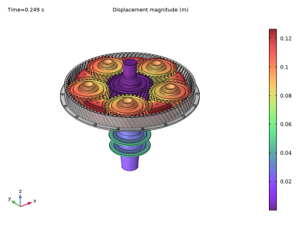
In the Settings window for 3D Plot Group, type Displacement: Fixed Sun Gear in the Label text field.
3
Locate the Data section. From the Dataset list, choose Study 2: Fixed Sun Gear/Solution 2 (sol2).
4
In the Displacement: Fixed Sun Gear toolbar, click  Plot.
Displacement: Fixed Carrier
1
Right-click Displacement: Fixed Ring Gear and choose Duplicate.
2
In the Settings window for 3D Plot Group, type Displacement: Fixed Carrier in the Label text field.
3
Locate the Data section. From the Dataset list, choose Study 3: Fixed Carrier/Solution 3 (sol3).
4
In the Displacement: Fixed Carrier toolbar, click  Plot.
Displacement: Fixed Carrier, Displacement: Fixed Ring Gear, Displacement: Fixed Sun Gear
1
In the Model Builder window, under Results, Ctrl-click to select Displacement: Fixed Ring Gear, Displacement: Fixed Sun Gear, and Displacement: Fixed Carrier.
2
Displacement
In the Settings window for Group, type Displacement in the Label text field.
Velocity: Fixed Ring Gear
1
In the Model Builder window, under Results click Velocity (mbd).
2
In the Settings window for 3D Plot Group, type Velocity: Fixed Ring Gear in the Label text field.
Follow the instructions below to plot the angular velocities of the sun gear, first planet gear, ring gear and carrier for different cases as shown in Figure 5, Figure 6, and Figure 7.
Graph Plot Style 1
1
In the Results toolbar, click  Configurations and choose Graph Plot Style.
2
In the Settings window for Graph Plot Style, locate the Coloring and Style section.
3
Find the Line style subsection. From the Width list, choose 2.
4
Locate the Legends section. Find the Include in automatic mode subsection. Clear the Headers checkbox.
5
Clear the Point checkbox.
6
Clear the Solution checkbox.
7
Select the Description checkbox.
Angular Velocity: Fixed Ring Gear
1
In the Results toolbar, click  1D Plot Group.
2
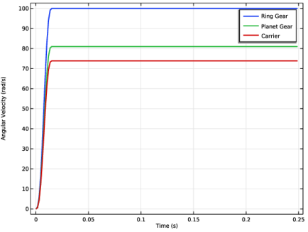
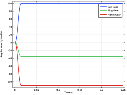
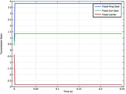
In the Settings window for 1D Plot Group, type Angular Velocity: Fixed Ring Gear in the Label text field.
3
Click to expand the Title section. From the Title type list, choose None.
4
Locate the Plot Settings section.
5
Select the y-axis label checkbox. In the associated text field, type Angular Velocity (rad/s).
6
Click to expand the Style Configuration section. From the Configuration list, choose Graph Plot Style 1.
Global 1
1
Right-click Angular Velocity: Fixed Ring Gear and choose Global.
2
In the Settings window for Global, locate the y-Axis Data section.
3
Angular Velocity: Fixed Ring Gear
1
In the Model Builder window, click Angular Velocity: Fixed Ring Gear.
2
In the Angular Velocity: Fixed Ring Gear toolbar, click  Plot.
Angular Velocity: Fixed Sun Gear
1
Right-click Angular Velocity: Fixed Ring Gear and choose Duplicate.
2
In the Settings window for 1D Plot Group, type Angular Velocity: Fixed Sun Gear in the Label text field.
3
Locate the Data section. From the Dataset list, choose None.
Global 1
1
In the Model Builder window, expand the Angular Velocity: Fixed Sun Gear node, then click Global 1.
2
In the Settings window for Global, locate the y-Axis Data section.
3
Angular Velocity: Fixed Sun Gear
1
In the Model Builder window, click Angular Velocity: Fixed Sun Gear.
2
In the Settings window for 1D Plot Group, locate the Data section.
3
From the Dataset list, choose Study 2: Fixed Sun Gear/Solution 2 (sol2).
4
In the Angular Velocity: Fixed Sun Gear toolbar, click  Plot.
Angular Velocity: Fixed Carrier
1
In the Model Builder window, right-click Angular Velocity: Fixed Ring Gear and choose Duplicate.
2
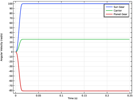
In the Settings window for 1D Plot Group, type Angular Velocity: Fixed Carrier in the Label text field.
3
Locate the Data section. From the Dataset list, choose None.
Global 1
1
In the Model Builder window, expand the Angular Velocity: Fixed Carrier node, then click Global 1.
2
In the Settings window for Global, locate the y-Axis Data section.
3
Angular Velocity: Fixed Carrier
1
In the Model Builder window, click Angular Velocity: Fixed Carrier.
2
In the Settings window for 1D Plot Group, locate the Data section.
3
From the Dataset list, choose Study 3: Fixed Carrier/Solution 3 (sol3).
4
In the Angular Velocity: Fixed Carrier toolbar, click  Plot.
Angular Velocity: Fixed Carrier, Angular Velocity: Fixed Ring Gear, Angular Velocity: Fixed Sun Gear
1
In the Model Builder window, under Results, Ctrl-click to select Angular Velocity: Fixed Ring Gear, Angular Velocity: Fixed Sun Gear, and Angular Velocity: Fixed Carrier.
2
Angular Velocity
In the Settings window for Group, type Angular Velocity in the Label text field.
Follow the instructions below to plot the transmission ratios for different configurations as shown in Figure 8.
1D Plot Group 8
In the Results toolbar, click  1D Plot Group.
Global 1
1
Right-click 1D Plot Group 8 and choose Global.
2
In the Settings window for Global, locate the y-Axis Data section.
3
Global 2
1
Right-click Global 1 and choose Duplicate.
2
In the Settings window for Global, locate the Data section.
3
From the Dataset list, choose Study 2: Fixed Sun Gear/Solution 2 (sol2).
4
Locate the y-Axis Data section. In the table, enter the following settings:
Global 3
1
Right-click Global 2 and choose Duplicate.
2
In the Settings window for Global, locate the Data section.
3
From the Dataset list, choose Study 3: Fixed Carrier/Solution 3 (sol3).
4
Locate the y-Axis Data section. In the table, enter the following settings:
Transmission Ratios
1
In the Model Builder window, under Results click 1D Plot Group 8.
2
In the Settings window for 1D Plot Group, type Transmission Ratios in the Label text field.
3
Locate the Title section. From the Title type list, choose None.
4
Locate the Plot Settings section.
5
Select the y-axis label checkbox. In the associated text field, type Transmission Ratio.
6
Locate the Style Configuration section. From the Configuration list, choose Graph Plot Style 1.
7
In the Transmission Ratios toolbar, click  Plot.
Follow the instructions below to plot the trajectory of different points in the planet gear as shown in Figure 9.
Planet Trajectory: Fixed Ring Gear
1
In the Results toolbar, click  1D Plot Group.
2
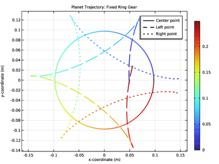
In the Settings window for 1D Plot Group, type Planet Trajectory: Fixed Ring Gear in the Label text field.
3
Locate the Title section. From the Title type list, choose Label.
4
Locate the Style Configuration section. From the Configuration list, choose Graph Plot Style 1.
Global 1
1
Right-click Planet Trajectory: Fixed Ring Gear and choose Global.
2
In the Settings window for Global, locate the y-Axis Data section.
3
4
Locate the x-Axis Data section. From the Parameter list, choose Expression.
5
In the Expression text field, type mbd.hlg3.xcx+mbd.hlg3.u.
6
Select the Description checkbox. In the associated text field, type x-coordinate.
7
Click to expand the Legends section. Click Override Settings in Style Configuration in the upper-right corner of the Legends section.
8
From the Legends list, choose Manual.
9
Color Expression 1
1
Right-click Global 1 and choose Color Expression.
2
In the Settings window for Color Expression, locate the Expression section.
3
In the Expression text field, type t.
Point Graph 1
1
In the Model Builder window, right-click Planet Trajectory: Fixed Ring Gear and choose Point Graph.
2
In the Model Builder window, click Point Graph 1.
3
4
In the Settings window for Point Graph, locate the y-Axis Data section.
5
In the Expression text field, type y.
6
Locate the x-Axis Data section. From the Parameter list, choose Expression.
7
In the Expression text field, type x.
8
Click to expand the Legends section. Click Override Settings in Style Configuration in the upper-right corner of the Legends section.
9
Select the Show legends checkbox.
10
From the Legends list, choose Manual.
11
12
Click to expand the Coloring and Style section. Find the Line style subsection. From the Line list, choose Dashed.
Color Expression 1
1
Right-click Point Graph 1 and choose Color Expression.
2
In the Settings window for Color Expression, locate the Expression section.
3
In the Expression text field, type t.
4
Locate the Coloring and Style section. Clear the Color legend checkbox.
Point Graph 2
1
In the Model Builder window, under Results > Planet Trajectory: Fixed Ring Gear right-click Point Graph 1 and choose Duplicate.
2
In the Settings window for Point Graph, locate the Selection section.
3
Click to select the  Activate Selection toggle button.
4
Click  Clear Selection.
5
6
Locate the Coloring and Style section. Find the Line style subsection. From the Line list, choose Dotted.
7
Locate the Legends section. In the table, enter the following settings:
Planet Trajectory: Fixed Ring Gear
1
In the Model Builder window, click Planet Trajectory: Fixed Ring Gear.
2
In the Settings window for 1D Plot Group, locate the Axis section.
3
Select the Preserve aspect ratio checkbox.
4
In the Planet Trajectory: Fixed Ring Gear toolbar, click  Plot.
Planet Trajectory: Fixed Sun Gear
1
Right-click Planet Trajectory: Fixed Ring Gear and choose Duplicate.
Follow the instructions below to plot the epicycloid curve traced by the planet gear, when sun gear is fixed as shown in Figure 10.
2
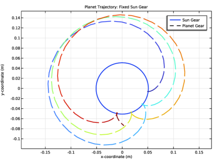
In the Settings window for 1D Plot Group, type Planet Trajectory: Fixed Sun Gear in the Label text field.
3
Locate the Data section. From the Dataset list, choose Study 2: Fixed Sun Gear/Solution 2 (sol2).
Global 1
1
In the Model Builder window, expand the Planet Trajectory: Fixed Sun Gear node, then click Global 1.
2
In the Settings window for Global, locate the y-Axis Data section.
3
4
Locate the x-Axis Data section. In the Expression text field, type mbd.grp6.xcp_pnx.
5
Locate the Legends section. In the table, enter the following settings:
Color Expression 1
1
In the Model Builder window, expand the Global 1 node.
2
Right-click Color Expression 1 and choose Delete.
Point Graph 1
1
In the Model Builder window, under Results > Planet Trajectory: Fixed Sun Gear click Point Graph 1.
2
In the Settings window for Point Graph, locate the Legends section.
3
Point Graph 2
In the Model Builder window, right-click Point Graph 2 and choose Delete.
Planet Trajectory: Fixed Sun Gear
1
In the Model Builder window, under Results click Planet Trajectory: Fixed Sun Gear.
2
In the Planet Trajectory: Fixed Sun Gear toolbar, click  Plot.
Planet Trajectory: Fixed Ring Gear, Planet Trajectory: Fixed Sun Gear
1
In the Model Builder window, under Results, Ctrl-click to select Planet Trajectory: Fixed Ring Gear and Planet Trajectory: Fixed Sun Gear.
2
Planet Trajectory
In the Settings window for Group, type Planet Trajectory in the Label text field.
Displacement: Fixed Ring Gear
1
In the Results toolbar, click  Animation and choose Player.
2
In the Settings window for Animation, type Displacement: Fixed Ring Gear in the Label text field.
3
Locate the Frames section. In the Number of frames text field, type 200.
Displacement: Fixed Sun Gear
1
Right-click Displacement: Fixed Ring Gear and choose Duplicate.
2
In the Settings window for Animation, type Displacement: Fixed Sun Gear in the Label text field.
3
Locate the Scene section. From the Subject list, choose Displacement: Fixed Sun Gear.
Displacement: Fixed Carrier
1
In the Model Builder window, right-click Displacement: Fixed Ring Gear and choose Duplicate.
2
In the Settings window for Animation, type Displacement: Fixed Carrier in the Label text field.
3
Locate the Scene section. From the Subject list, choose Displacement: Fixed Carrier.