|
|
|
|
•
|
|
•
|
|
•
|
|
30 kg
|
||
|
120 kg
|
||
|
•
|
Fixed Node is the default node of the Lumped Mechanical System interface. It can however be disabled if none of the nodes of the system is fixed.
|
|
•
|
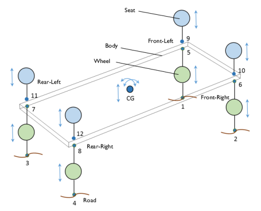
To re-use the lumped model definition of a wheel and seat of a vehicle, use a Subsystem Definition node to define the component once. Then, use Subsystem Instance nodes multiple times to create more than one instance of the wheels and seats.
|
|
•
|
The Lumped–Structure Connection multiphysics coupling and External Source node can be used to connect a distributed model of a component to the lumped model of the system.
|
|
•
|
To restrict the number of degrees of freedom of the vehicle body to be only three, the Prescribed Displacement/Rotation subnode of the Rigid Material node is used.
|
|
•
|
To enter the lumped mass and inertia values of a vehicle body, the Mass and Moment of Inertia subnode of the Rigid Material node is used.
|
|
1
|
|
2
|
|
3
|
Click Add.
|
|
4
|
|
5
|
Click Add.
|
|
6
|
Click
|
|
7
|
|
8
|
Click
|
|
1
|
|
2
|
|
3
|
Click
|
|
4
|
Browse to the model’s Application Libraries folder and double-click the file lumped_vehicle_suspension_system_parameters.txt.
|
|
1
|
|
2
|
|
3
|
|
4
|
|
5
|
|
6
|
|
7
|
|
1
|
|
2
|
|
3
|
|
1
|
|
2
|
|
3
|
|
4
|
|
5
|
|
6
|
|
7
|
Click
|
|
1
|
|
2
|
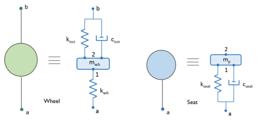
In the Settings window for Subsystem Definition, type Subsystem Definition: Wheel in the Label text field.
|
|
1
|
|
2
|
|
4
|
|
1
|
|
2
|
|
4
|
|
1
|
|
2
|
|
4
|
|
1
|
|
2
|
|
4
|
|
1
|
|
2
|
In the Settings window for Subsystem Definition, type Subsystem Definition: Seat in the Label text field.
|
|
1
|
|
2
|
|
4
|
|
1
|
|
2
|
|
4
|
|
1
|
|
2
|
|
3
|
Locate the Node Connections section. In the table, enter the following settings:
|
|
4
|
|
1
|
|
2
|
In the Settings window for Displacement Node, type Displacement Node: Front-Left in the Label text field.
|
|
3
|
|
1
|
|
2
|
In the Settings window for Displacement Node, type Displacement Node: Front-Right in the Label text field.
|
|
3
|
|
1
|
|
2
|
In the Settings window for Displacement Node, type Displacement Node: Rear-Left in the Label text field.
|
|
3
|
|
1
|
|
2
|
In the Settings window for Displacement Node, type Displacement Node: Rear-Right in the Label text field.
|
|
3
|
|
1
|
|
2
|
In the Settings window for Subsystem Instance, type Subsystem Instance X1: Front-Left Wheel in the Label text field.
|
|
3
|
Locate the Node Connections section. From the Name of subsystem link list, choose Subsystem Definition: Wheel (sub1).
|
|
1
|
|
2
|
In the Settings window for External Source, type External Source E1: Front-Left in the Label text field.
|
|
3
|
Locate the Node Connections section. In the table, enter the following settings:
|
|
4
|
Locate the Component Parameters section. From the Input displacement list, choose From multiphysics coupling.
|
|
5
|
Locate the Results section. Find the Add the following to default results subsection. Clear the Force checkbox.
|
|
6
|
Clear the Displacement checkbox.
|
|
1
|
|
2
|
In the Settings window for Subsystem Instance, type Subsystem Instance X5: Front-Left Seat in the Label text field.
|
|
3
|
Locate the Node Connections section. From the Name of subsystem link list, choose Subsystem Definition: Seat (sub2).
|
|
1
|
|
3
|
|
4
|
From the ρ list, choose User defined. Locate the Center of Rotation section. From the list, choose User defined.
|
|
1
|
|
2
|
In the Settings window for Mass and Moment of Inertia, locate the Mass and Moment of Inertia section.
|
|
3
|
|
4
|
From the list, choose Diagonal.
|
|
5
|
Specify the I matrix as
|
|
1
|
|
2
|
In the Settings window for Prescribed Displacement/Rotation, locate the Prescribed Displacement at Center of Rotation section.
|
|
3
|
Select the Prescribed in x direction checkbox.
|
|
4
|
Select the Prescribed in y direction checkbox.
|
|
5
|
|
6
|
Select the Constrain rotation around z-axis checkbox.
|
|
1
|
In the Physics toolbar, click
|
|
2
|
In the Settings window for Lumped–Structure Connection, type Lumped-Structure Connection: Front-Left in the Label text field.
|
|
4
|
|
1
|
In the Physics toolbar, click
|
|
2
|
In the Settings window for Lumped–Structure Connection, type Lumped-Structure Connection: Front-Right in the Label text field.
|
|
4
|
|
6
|
|
1
|
In the Physics toolbar, click
|
|
2
|
In the Settings window for Lumped–Structure Connection, type Lumped-Structure Connection: Rear-Left in the Label text field.
|
|
4
|
|
6
|
|
1
|
In the Physics toolbar, click
|
|
2
|
In the Settings window for Lumped–Structure Connection, type Lumped-Structure Connection: Rear-Right in the Label text field.
|
|
4
|
|
6
|
|
1
|
|
2
|
|
3
|
|
1
|
|
2
|
|
3
|
In the Model Builder window, under Study 1 > Solver Configurations > Solution 1 (sol1) click Time-Dependent Solver 1.
|
|
4
|
|
5
|
Find the Algebraic variable settings subsection. From the Error estimation list, choose Exclude algebraic.
|
|
6
|
Right-click Study 1 > Solver Configurations > Solution 1 (sol1) > Time-Dependent Solver 1 and choose Fully Coupled.
|
|
7
|
|
8
|
|
9
|
|
10
|
|
1
|
|
2
|
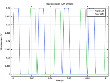
In the Settings window for 1D Plot Group, type Road Excitation (Left Wheels) in the Label text field.
|
|
3
|
|
4
|
|
5
|
|
1
|
|
2
|
In the Settings window for Global, click Replace Expression in the upper-right corner of the y-Axis Data section. From the menu, choose Component 1 (comp1) > Lumped Mechanical System > Node displacements > lms.u_1 - Displacement at node u_1 - m.
|
|
3
|
Click Add Expression in the upper-right corner of the y-Axis Data section. From the menu, choose Component 1 (comp1) > Lumped Mechanical System > Node displacements > lms.u_3 - Displacement at node u_3 - m.
|
|
4
|
Locate the y-Axis Data section. In the table, enter the following settings:
|
|
1
|
|
2
|
|
3
|
|
4
|
|
5
|
|
1
|
|
2
|
|
3
|
|
4
|
|
1
|
|
2
|
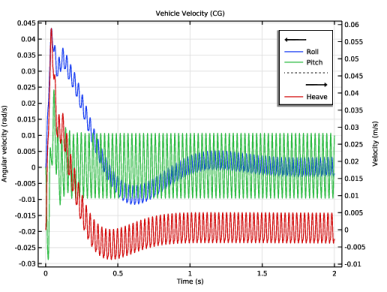
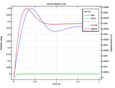
In the Settings window for Global, click Replace Expression in the upper-right corner of the y-Axis Data section. From the menu, choose Component 1 (comp1) > Multibody Dynamics > Rigid domains > Rigid Material 1 > Rigid body rotation (spatial frame) - rad > mbd.rd1.thx - Rigid body rotation, x-component.
|
|
3
|
Click Add Expression in the upper-right corner of the y-Axis Data section. From the menu, choose Component 1 (comp1) > Multibody Dynamics > Rigid domains > Rigid Material 1 > Rigid body rotation (spatial frame) - rad > mbd.rd1.thy - Rigid body rotation, y-component.
|
|
4
|
Locate the y-Axis Data section. In the table, enter the following settings:
|
|
1
|
|
2
|
In the Settings window for Global, click Replace Expression in the upper-right corner of the y-Axis Data section. From the menu, choose Component 1 (comp1) > Multibody Dynamics > Rigid domains > Rigid Material 1 > Rigid body displacement (spatial frame) - m > mbd.rd1.w - Rigid body displacement, z-component.
|
|
3
|
Locate the y-Axis Data section. In the table, enter the following settings:
|
|
4
|
|
1
|
|
2
|
|
3
|
|
4
|
|
5
|
|
6
|
|
1
|
|
2
|
|
3
|
|
4
|
|
1
|
|
2
|
|
1
|
|
2
|
|
1
|
|
2
|
|
3
|
|
1
|
|
2
|
|
3
|
|
1
|
|
2
|
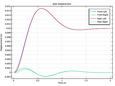
In the Settings window for Global, click Replace Expression in the upper-right corner of the y-Axis Data section. From the menu, choose Component 1 (comp1) > Lumped Mechanical System > Terminals > lms.X5.m1.u - Displacement (m1) - m.
|
|
3
|
Click Add Expression in the upper-right corner of the y-Axis Data section. From the menu, choose Component 1 (comp1) > Lumped Mechanical System > Terminals > lms.X6.m1.u - Displacement (m1) - m.
|
|
4
|
Click Add Expression in the upper-right corner of the y-Axis Data section. From the menu, choose Component 1 (comp1) > Lumped Mechanical System > Terminals > lms.X7.m1.u - Displacement (m1) - m.
|
|
5
|
Click Add Expression in the upper-right corner of the y-Axis Data section. From the menu, choose Component 1 (comp1) > Lumped Mechanical System > Terminals > lms.X8.m1.u - Displacement (m1) - m.
|
|
6
|
Locate the y-Axis Data section. In the table, enter the following settings:
|
|
1
|
|
2
|
|
3
|
|
4
|
|
5
|
|
1
|
|
2
|
|
3
|
|
1
|
|
2
|
|
1
|
|
2
|
|
3
|
|
1
|
|
2
|
|
3
|
|
1
|
|
2
|
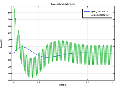
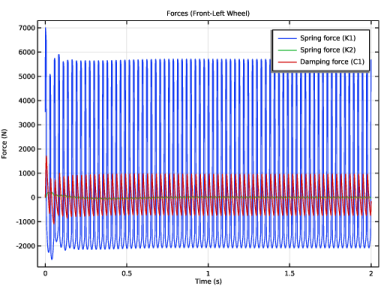
In the Settings window for Global, click Replace Expression in the upper-right corner of the y-Axis Data section. From the menu, choose Component 1 (comp1) > Lumped Mechanical System > Subsystem X1 > Two port components > K1 > lms.X1.K1.f - Spring force (K1) - N.
|
|
3
|
Click Add Expression in the upper-right corner of the y-Axis Data section. From the menu, choose Component 1 (comp1) > Lumped Mechanical System > Subsystem X1 > Two port components > K2 > lms.X1.K2.f - Spring force (K2) - N.
|
|
4
|
Click Add Expression in the upper-right corner of the y-Axis Data section. From the menu, choose Component 1 (comp1) > Lumped Mechanical System > Subsystem X1 > Two port components > C1 > lms.X1.C1.f - Damping force (C1) - N.
|
|
1
|
|
2
|
|
3
|
|
4
|
|
5
|
|
1
|
|
2
|
|
3
|
|
1
|
|
2
|
In the Settings window for Global, click Replace Expression in the upper-right corner of the y-Axis Data section. From the menu, choose Component 1 (comp1) > Lumped Mechanical System > Subsystem X5 > Two port components > K1 > lms.X5.K1.f - Spring force (K1) - N.
|
|
3
|
Click Add Expression in the upper-right corner of the y-Axis Data section. From the menu, choose Component 1 (comp1) > Lumped Mechanical System > Subsystem X5 > Two port components > C1 > lms.X5.C1.f - Damping force (C1) - N.
|
|
1
|
|
2
|
|
3
|
|
4
|
|
5
|