|
|
|
|
•
|
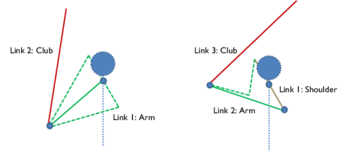
In this model, linkages are modeled as rigid elements using Rigid Material nodes as we are only interested in the kinematics of the mechanism. Linkages can be modeled as flexible elements using the Linear Elastic Material node if the stresses and deformations in the linkages are also of interest.
|
|
•
|
The Mass and Moment of Inertia subnode of the Rigid Material node is used to enter the inertia properties given at a certain point.
|
|
•
|
The connections set up in the model can be reviewed in the Joints Summary section at the physics node.
|
|
1
|
|
2
|
|
3
|
Click Add.
|
|
4
|
Click
|
|
5
|
|
6
|
Click
|
|
1
|
|
2
|
|
3
|
Click
|
|
4
|
Browse to the model’s Application Libraries folder and double-click the file golf_swing_mechanics_parameters.txt.
|
|
1
|
|
2
|
|
3
|
Click
|
|
4
|
Browse to the model’s Application Libraries folder and double-click the file golf_swing_mechanics.mphbin.
|
|
5
|
Click
|
|
1
|
|
2
|
|
3
|
|
4
|
Clear the Create pairs checkbox.
|
|
5
|
|
1
|
|
2
|
|
3
|
|
1
|
|
2
|
|
3
|
Click
|
|
4
|
Browse to the model’s Application Libraries folder and double-click the file golf_swing_mechanics_variables.txt.
|
|
1
|
|
2
|
|
4
|
|
1
|
|
2
|
In the Settings window for Mass and Moment of Inertia, locate the Mass and Moment of Inertia section.
|
|
3
|
|
1
|
|
2
|
|
4
|
|
1
|
|
2
|
|
3
|
From the list, choose Centroid of selected entities.
|
|
4
|
|
5
|
|
6
|
|
1
|
|
1
|
|
2
|
|
4
|
|
1
|
|
2
|
|
3
|
From the list, choose Centroid of selected entities.
|
|
4
|
|
5
|
|
6
|
|
1
|
|
1
|
|
2
|
|
4
|
|
1
|
|
2
|
|
3
|
From the list, choose Centroid of selected entities.
|
|
4
|
|
5
|
|
6
|
|
1
|
|
1
|
In the Model Builder window, under Component 1 (comp1) > Multibody Dynamics (mbd), Ctrl-click to select Rigid Material: Shoulder, Rigid Material: Arm, Rigid Material: Grip, and Rigid Material: Club.
|
|
2
|
Right-click and choose Group.
|
|
1
|
|
2
|
|
3
|
|
4
|
|
1
|
|
1
|
|
2
|
|
3
|
From the list, choose Joint.
|
|
4
|
|
1
|
|
2
|
|
3
|
|
4
|
|
1
|
|
1
|
|
2
|
|
3
|
|
4
|
|
1
|
|
2
|
|
3
|
From the list, choose Joint.
|
|
4
|
|
1
|
|
2
|
|
3
|
|
4
|
|
1
|
|
1
|
|
2
|
|
3
|
|
4
|
|
1
|
|
2
|
|
3
|
From the list, choose Joint.
|
|
4
|
|
1
|
|
2
|
|
3
|
|
4
|
|
1
|
|
1
|
|
2
|
|
3
|
|
4
|
|
1
|
In the Model Builder window, under Component 1 (comp1) > Multibody Dynamics (mbd), Ctrl-click to select Hinge Joint: Shoulder, Hinge Joint: Arm, Hinge Joint: Wrist, and Hinge Joint: Shaft.
|
|
2
|
Right-click and choose Group.
|
|
1
|
|
2
|
|
1
|
|
2
|
|
3
|
Click
|
|
1
|
|
2
|
|
3
|
|
1
|
|
2
|
|
3
|
Right-click Study 1 > Solver Configurations > Solution 1 (sol1) > Time-Dependent Solver 1 and choose Stop Condition.
|
|
4
|
|
5
|
Click
|
|
7
|
|
8
|
|
1
|
|
3
|
|
4
|
|
1
|
|
2
|
|
3
|
|
4
|
|
5
|
|
6
|
|
1
|
|
2
|
|
3
|
|
4
|
|
5
|
Locate the Plot Settings section.
|
|
6
|
|
7
|
|
1
|
|
3
|
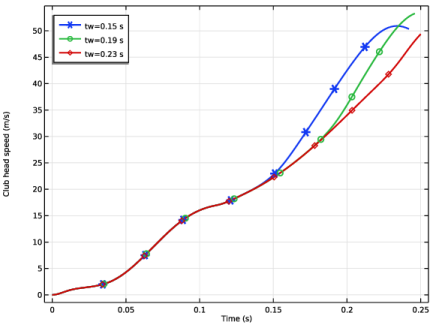
In the Settings window for Point Graph, click Replace Expression in the upper-right corner of the y-Axis Data section. From the menu, choose Component 1 (comp1) > Multibody Dynamics > Acceleration and velocity > mbd.vel - Velocity magnitude - m/s.
|
|
4
|
|
5
|
|
6
|
|
7
|
|
8
|
|
9
|
|
10
|
|
11
|
|
1
|
|
2
|
|
3
|
|
4
|
|
5
|
|
6
|
|
7
|
Locate the Plot Settings section.
|
|
8
|
|
1
|
|
2
|
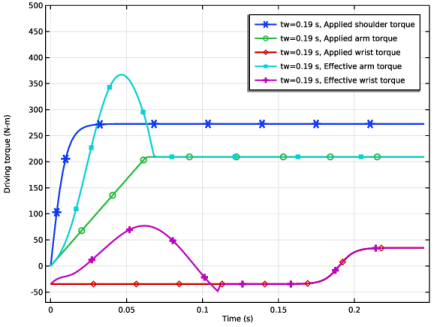
In the Settings window for Global, click Replace Expression in the upper-right corner of the y-Axis Data section. From the menu, choose Component 1 (comp1) > Definitions > Variables > Tsh - Applied shoulder torque - N·m.
|
|
3
|
Click Add Expression in the upper-right corner of the y-Axis Data section. From the menu, choose Component 1 (comp1) > Definitions > Variables > Ta - Applied arm torque - N·m.
|
|
4
|
Click Add Expression in the upper-right corner of the y-Axis Data section. From the menu, choose Component 1 (comp1) > Definitions > Variables > Tw - Applied wrist torque - N·m.
|
|
5
|
Click Add Expression in the upper-right corner of the y-Axis Data section. From the menu, choose Component 1 (comp1) > Definitions > Variables > Ta_eff - Effective arm torque - N·m.
|
|
6
|
Click Add Expression in the upper-right corner of the y-Axis Data section. From the menu, choose Component 1 (comp1) > Definitions > Variables > Tw_eff - Effective wrist torque - N·m.
|
|
7
|
|
8
|
|
9
|
|
1
|
|
2
|
|
3
|
Select the Manual axis limits checkbox.
|
|
4
|
|
5
|
|
6
|
|
1
|
|
2
|
|
3
|
|
4
|
|
1
|
|
2
|
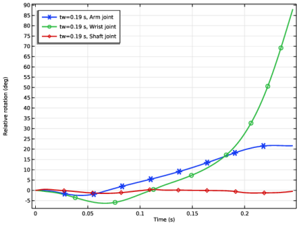
In the Settings window for Global, click Replace Expression in the upper-right corner of the y-Axis Data section. From the menu, choose Component 1 (comp1) > Multibody Dynamics > Hinge joints > Hinge Joint: Arm > mbd.hgj2.th - Relative rotation - rad.
|
|
3
|
Locate the y-Axis Data section. In the table, enter the following settings:
|
|
4
|
Click Add Expression in the upper-right corner of the y-Axis Data section. From the menu, choose Component 1 (comp1) > Multibody Dynamics > Hinge joints > Hinge Joint: Wrist > mbd.hgj3.th - Relative rotation - rad.
|
|
5
|
Locate the y-Axis Data section. In the table, enter the following settings:
|
|
6
|
Click Add Expression in the upper-right corner of the y-Axis Data section. From the menu, choose Component 1 (comp1) > Multibody Dynamics > Hinge joints > Hinge Joint: Shaft > mbd.hgj4.th - Relative rotation - rad.
|
|
7
|
Locate the y-Axis Data section. In the table, enter the following settings:
|
|
8
|
|
9
|
|
1
|
|
2
|
|
1
|
|
2
|
|
3
|
|
4
|
|
5
|
|
6
|
|
7
|
|
8
|
|
9
|
|
10
|
Click OK.
|
|
11
|
|
12
|
|
13
|
|
14
|
|
15
|
|
16
|
|
1
|
|
2
|
|
3
|
|
4
|
|
5
|
|
6
|
|
7
|
|
8
|
|
9
|
|
10
|
Click OK.
|
|
11
|
|
12
|
|
13
|
|
14
|
|
15
|
|
16
|
|
17
|
|
1
|
In the Model Builder window, under Results > Shoulder-arm-club Motion right-click Line Graph 1 and choose Duplicate.
|
|
2
|
|
3
|
|
4
|
|
1
|
In the Model Builder window, under Results > Shoulder-arm-club Motion right-click Point Graph 1 and choose Duplicate.
|
|
2
|
|
3
|
|
4
|
|
1
|
In the Model Builder window, under Results > Shoulder-arm-club Motion right-click Line Graph 2 and choose Duplicate.
|
|
2
|
|
3
|
|
4
|
|
1
|
In the Model Builder window, under Results > Shoulder-arm-club Motion right-click Point Graph 2 and choose Duplicate.
|
|
2
|
|
3
|
|
4
|
|
5
|
|
6
|
|
1
|
|
2
|
|
3
|
|
4
|
Locate the Plot Settings section.
|
|
5
|
|
6
|
|
7
|
|
8
|