
|
|
|
|
•
|
Modulus of elasticity: 70 GPa
|
|
•
|
Poisson’s ratio: 0.33.
|
|
•
|
|
•
|
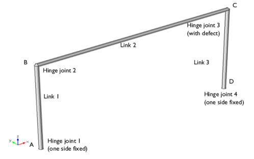
In this model, the links are modeled as flexible parts using the Linear Elastic Material node. Modeling the links as rigid locks the assembly.
|
|
•
|
A Joint can have one side fixed by selecting the Source as Fixed. In this way you can avoid creating an extra geometry components for the “ground”.
|
|
1
|
|
2
|
|
3
|
Click Add.
|
|
4
|
Click
|
|
5
|
|
6
|
Click
|
|
1
|
|
2
|
|
1
|
|
2
|
|
3
|
|
4
|
|
1
|
|
2
|
|
3
|
|
1
|
In the Model Builder window, under Component 1 (comp1) > Geometry 1 right-click Cylinder 1 (cyl1) and choose Duplicate.
|
|
2
|
|
3
|
|
4
|
|
5
|
|
1
|
|
2
|
|
3
|
|
4
|
|
5
|
|
1
|
In the Model Builder window, under Component 1 (comp1) right-click Materials and choose Blank Material.
|
|
2
|
|
1
|
|
2
|
|
3
|
|
1
|
|
1
|
|
2
|
|
3
|
|
4
|
|
5
|
|
6
|
|
1
|
|
1
|
|
1
|
In the Model Builder window, under Component 1 (comp1) > Multibody Dynamics (mbd) right-click Hinge Joint 1 and choose Duplicate.
|
|
2
|
|
3
|
|
4
|
|
1
|
|
1
|
|
1
|
In the Model Builder window, under Component 1 (comp1) > Multibody Dynamics (mbd) right-click Hinge Joint 2 and choose Duplicate.
|
|
2
|
|
3
|
|
4
|
|
5
|
|
6
|
|
1
|
|
1
|
In the Model Builder window, under Component 1 (comp1) > Multibody Dynamics (mbd) right-click Hinge Joint 1 and choose Duplicate.
|
|
2
|
|
3
|
|
1
|
|
2
|
|
3
|
|
4
|
|
1
|
In the Model Builder window, under Component 1 (comp1) > Multibody Dynamics (mbd), Ctrl-click to select Attachment 1, Attachment 2, Attachment 3, Attachment 4, Attachment 5, and Attachment 6.
|
|
2
|
Right-click and choose Group.
|
|
1
|
In the Model Builder window, under Component 1 (comp1) > Multibody Dynamics (mbd), Ctrl-click to select Hinge Joint 1, Hinge Joint 2, Hinge Joint 3, and Hinge Joint 4.
|
|
2
|
Right-click and choose Group.
|
|
1
|
|
2
|
|
1
|
|
2
|
|
3
|
|
1
|
|
3
|
|
4
|
|
1
|
|
3
|
|
4
|
|
5
|
|
1
|
|
2
|
|
3
|
|
4
|
|
1
|
|
1
|
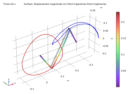
In the Model Builder window, expand the Results > Displacement (mbd) > Surface node, then click Deformation.
|
|
2
|
|
3
|
|
1
|
|
2
|
|
3
|
|
5
|
Locate the Coloring and Style section. Find the Line style subsection. From the Type list, choose Tube.
|
|
1
|
|
2
|
|
3
|
Click
|
|
5
|
Locate the Coloring and Style section. Find the Line style subsection. From the Color list, choose Blue.
|
|
6
|
|
1
|
|
2
|
|
3
|
|
1
|
|
2
|
|
3
|
|
4
|
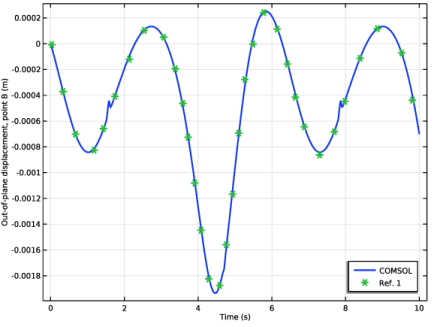
Browse to the model’s Application Libraries folder and double-click the file crooked_four_bar_mechanism_vB.txt.
|
|
1
|
|
2
|
|
3
|
|
4
|
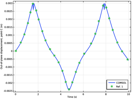
Browse to the model’s Application Libraries folder and double-click the file crooked_four_bar_mechanism_vC.txt.
|
|
1
|
|
2
|
|
1
|
|
3
|
|
4
|
|
5
|
|
6
|
|
7
|
|
1
|
|
2
|
|
3
|
|
4
|
|
5
|
|
6
|
|
1
|
|
2
|
|
3
|
|
4
|
|
5
|
Locate the Plot Settings section.
|
|
6
|
|
7
|
Select the y-axis label checkbox. In the associated text field, type Out-of-plane displacement, point B (m).
|
|
8
|
|
1
|
|
2
|
|
1
|
|
2
|
|
3
|
Click to select the
|
|
1
|
|
2
|
|
3
|
|
1
|
|
2
|
|
3
|
|
4
|
|
1
|
|
2
|
|
3
|