
|
|
|
|
(0, 0, 0) mm
|
(0, -10, 50) mm
|
||
|
(0, -1, 0)
|
(0, 0, -1)
|
|
•
|
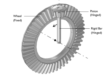
A resisting torque of 10 N·m is applied at the joint between pinion and the rigid bar.
|
|
•
|
To build a gear geometry, you can import a gear part from the Parts Library and customize it by changing its input parameters. Alternatively, you can also create an equivalent disc or cone to represent the gear.
|
|
•
|
All the gears are assumed rigid. The elasticity of a gear mesh can be included on Gear Pair nodes using the Gear Elasticity subnode.
|
|
•
|
All the Gear Pair nodes are assumed ideal and frictionless. You can add Transmission Error, Backlash, or Friction subnodes when required.
|
|
•
|
To constrain the motion of a gear, you can use Prescribed Displacement/Rotation or Fixed Constraint subnodes. Alternatively, you can mount the gears on a shaft or on the ground through various Joint nodes.
|
|
•
|
The contact force on a Gear Pair is computed using Weak constraints or Penalty method. By default, the contact force computation is turned off. Use the weak constraints method for more accurate contact forces; however, you can, preferably, switch to the penalty method for large rigid body systems.
|
|
1
|
|
2
|
|
3
|
Click Add.
|
|
4
|
Click
 Study. Study. |
|
5
|
|
6
|
Click
 Done. Done. |
|
1
|
|
2
|
|
3
|
Click
 Load from File. Load from File. |
|
4
|
Browse to the model’s Application Libraries folder and double-click the file bevel_gear_pair_parameters.txt.
|
|
1
|
|
2
|
In the Part Libraries window, select Multibody Dynamics Module > 3D > External Gears > bevel_gear in the tree.
|
|
3
|
Click
 Add to Geometry. Add to Geometry. |
|
1
|
|
2
|
|
3
|
|
1
|
|
2
|
|
1
|
|
2
|
|
3
|
|
4
|
|
5
|
|
6
|
|
7
|
|
8
|
|
9
|
|
1
|
|
2
|
|
3
|
|
4
|
Clear the Create pairs checkbox.
|
|
5
|
|
6
|
|
7
|
|
8
|
Clear the Automatic detection of small details checkbox.
|
|
1
|
|
2
|
In the Settings window for Multibody Dynamics, click Physics Node Generation in the upper-right corner of the Automated Model Setup section. From the menu, choose Create Gears.
|
|
1
|
|
2
|
|
3
|
|
1
|
|
2
|
|
3
|
Select the Evaluate reaction forces checkbox.
|
|
1
|
In the Model Builder window, under Component 1 (comp1) > Multibody Dynamics (mbd) > Gears click Bevel Gear 2.
|
|
2
|
|
3
|
|
1
|
|
2
|
|
3
|
|
4
|
|
5
|
Locate the Contact Force Computation section. From the list, choose Computed using weak constraints.
|
|
1
|
|
3
|
|
4
|
|
1
|
|
2
|
|
3
|
|
4
|
|
5
|
|
6
|
|
1
|
|
2
|
|
3
|
Click
 Paste Selection. Paste Selection. |
|
4
|
|
5
|
Click OK.
|
|
1
|
|
2
|
|
3
|
|
1
|
|
2
|
|
3
|
From the list, choose Joint.
|
|
4
|
|
1
|
|
2
|
|
3
|
|
4
|
|
5
|
|
1
|
|
2
|
|
3
|
Click
 Paste Selection. Paste Selection. |
|
4
|
|
5
|
Click OK.
|
|
1
|
|
2
|
|
3
|
|
1
|
|
2
|
|
3
|
|
1
|
In the Model Builder window, under Component 1 (comp1) > Multibody Dynamics (mbd), Ctrl-click to select Hinge Joint 1 and Hinge Joint 2.
|
|
2
|
Right-click and choose Group.
|
|
1
|
|
2
|
|
1
|
|
2
|
|
3
|
|
4
|
|
1
|
|
2
|
|
3
|
|
4
|
|
1
|
|
2
|
|
1
|
|
2
|
|
3
|
|
4
|
Click Replace Expression in the upper-right corner of the Expressions section. From the menu, choose Component 1 (comp1) > Multibody Dynamics > Gear pairs > Gear Pair 1 > mbd.grp1.Fc - Force at contact point - N.
|
|
5
|
Click
 Evaluate. Evaluate. |
|
1
|
|
2
|
|
3
|
|
4
|
Click Replace Expression in the upper-right corner of the Expressions section. From the menu, choose Component 1 (comp1) > Multibody Dynamics > Bevel gears > Bevel Gear 1 > Reaction force (spatial frame) - N > mbd.bvg1.RFx - Reaction force, x-component.
|
|
5
|
Click Add Expression in the upper-right corner of the Expressions section. From the menu, choose Component 1 (comp1) > Multibody Dynamics > Bevel gears > Bevel Gear 1 > Reaction force (spatial frame) - N > mbd.bvg1.RFy - Reaction force, y-component.
|
|
6
|
Click Add Expression in the upper-right corner of the Expressions section. From the menu, choose Component 1 (comp1) > Multibody Dynamics > Bevel gears > Bevel Gear 1 > Reaction force (spatial frame) - N > mbd.bvg1.RFz - Reaction force, z-component.
|
|
7
|
|
1
|
|
2
|
|
3
|
|
4
|
Click Replace Expression in the upper-right corner of the Expressions section. From the menu, choose Component 1 (comp1) > Multibody Dynamics > Bevel gears > Bevel Gear 1 > Reaction moment (spatial frame) - N·m > mbd.bvg1.RMx - Reaction moment, x-component.
|
|
5
|
Click Add Expression in the upper-right corner of the Expressions section. From the menu, choose Component 1 (comp1) > Multibody Dynamics > Bevel gears > Bevel Gear 1 > Reaction moment (spatial frame) - N·m > mbd.bvg1.RMy - Reaction moment, y-component.
|
|
6
|
Click Add Expression in the upper-right corner of the Expressions section. From the menu, choose Component 1 (comp1) > Multibody Dynamics > Bevel gears > Bevel Gear 1 > Reaction moment (spatial frame) - N·m > mbd.bvg1.RMz - Reaction moment, z-component.
|
|
7
|
|
1
|
|
2
|
|
1
|
|
2
|
In the Settings window for Global, click Replace Expression in the upper-right corner of the y-Axis Data section. From the menu, choose Component 1 (comp1) > Multibody Dynamics > Bevel gears > Bevel Gear 1 > Reaction force (spatial frame) - N > mbd.bvg1.RFx - Reaction force, x-component.
|
|
3
|
Click Add Expression in the upper-right corner of the y-Axis Data section. From the menu, choose Component 1 (comp1) > Multibody Dynamics > Bevel gears > Bevel Gear 1 > Reaction force (spatial frame) - N > mbd.bvg1.RFy - Reaction force, y-component.
|
|
4
|
Click Add Expression in the upper-right corner of the y-Axis Data section. From the menu, choose Component 1 (comp1) > Multibody Dynamics > Bevel gears > Bevel Gear 1 > Reaction force (spatial frame) - N > mbd.bvg1.RFz - Reaction force, z-component.
|
|
5
|
|
1
|
|
2
|
|
3
|
|
4
|
Locate the Plot Settings section.
|
|
5
|
|
6
|
|
7
|
|
8
|
|
1
|
|
2
|
|
1
|
|
2
|
In the Settings window for Global, click Replace Expression in the upper-right corner of the y-Axis Data section. From the menu, choose Component 1 (comp1) > Multibody Dynamics > Bevel gears > Bevel Gear 1 > Reaction moment (spatial frame) - N·m > mbd.bvg1.RMx - Reaction moment, x-component.
|
|
3
|
Click Add Expression in the upper-right corner of the y-Axis Data section. From the menu, choose Component 1 (comp1) > Multibody Dynamics > Bevel gears > Bevel Gear 1 > Reaction moment (spatial frame) - N·m > mbd.bvg1.RMy - Reaction moment, y-component.
|
|
4
|
Click Add Expression in the upper-right corner of the y-Axis Data section. From the menu, choose Component 1 (comp1) > Multibody Dynamics > Bevel gears > Bevel Gear 1 > Reaction moment (spatial frame) - N·m > mbd.bvg1.RMz - Reaction moment, z-component.
|
|
5
|
|
1
|
|
2
|
|
3
|
|
4
|
Locate the Plot Settings section.
|
|
5
|
|
6
|
|
7
|
|
1
|
|
2
|
|
1
|
|
2
|
Click Yes to confirm.
|
|
1
|
|
2
|
|
3
|
|
4
|
|
1
|
|
2
|
|
3
|


 next to

 next to


